Toyota Sequoia (2005). Manual — part 148
–
DIAGNOSTICS
ENGINE
DI–387
581
MONITOR STRATEGY
P2195
A/F sensor (Bank 1) signal stuck lean
P2195
A/F sensor (Bank 1) current (high side)
P2196
A/F sensor (Bank 1) signal stuck rich
R l t d DTC
P2196
A/F sensor (Bank 1) current (low side)
Related DTCs
P2197
A/F sensor (Bank 2) signal stuck lean
P2197
A/F sensor (Bank 2) current (high side)
P2198
A/F sensor (Bank 2) signal stuck rich
P2198
A/F sensor (Bank 2) current (low side)
Required sensors/components
A/F sensor
Frequency of operation
Once per driving cycle
Duration
15 sec.: A/F sensor signal stuck lean/rich
3 sec.: A/F sensor current (high/low side)
MIL operation
2 driving cycles
Sequence of operation
None
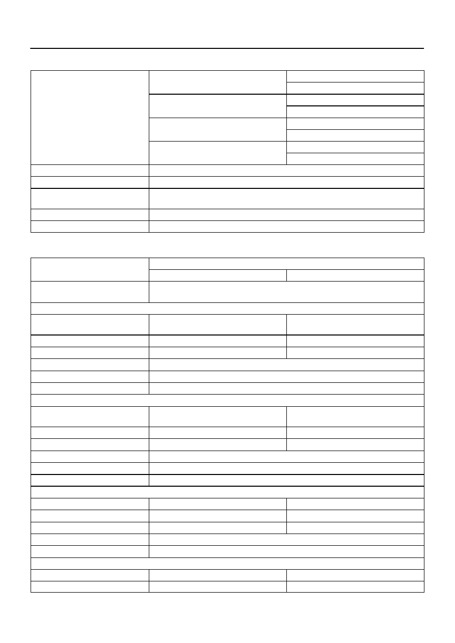
TYPICAL ENABLING CONDITIONS
It
Specification
Item
Minimum
Maximum
The monitor will run whenever these
DTCs are not present
See page
P2195, P2197 (A/F sensor signal stuck lean):
Duration while all of following conditions
met
2 sec.
–
Rear HO2S voltage
0.15 V
–
Time after engine start
30 sec.
–
A/F sensor status
Activated
Fuel system status
Closed–loop
Engine
Running
P2196, P2198 (A/F sensor signal stuck rich):
Duration while all of following conditions
met
2 sec.
–
Rear HO2S voltage
–
0.6 V
Time after engine start
30 sec.
–
A/F sensor status
Activated
Fuel system status
Closed–loop
Engine
Running
P2195, P2197 (A/F sensor current (High side)):
Battery voltage
11 V
–
ECT
75
°
C (167
°
F)
–
Atmospheric pressure/760 mmHg
0.75
–
A/F sensor status
Activated
Continuous time of fuel–cut
3 to 10 sec.
P2196, P2198 (A/F sensor current (Low side)):
Battery voltage
11 V
–
ECT
75
°
C (167
°
F)
–
DI–388
–
DIAGNOSTICS
ENGINE
582
Atmospheric pressure/760 mmHg
0.75
–
A/F sensor status
Activated
Continuous time of fuel–cut
3 to 10 sec.
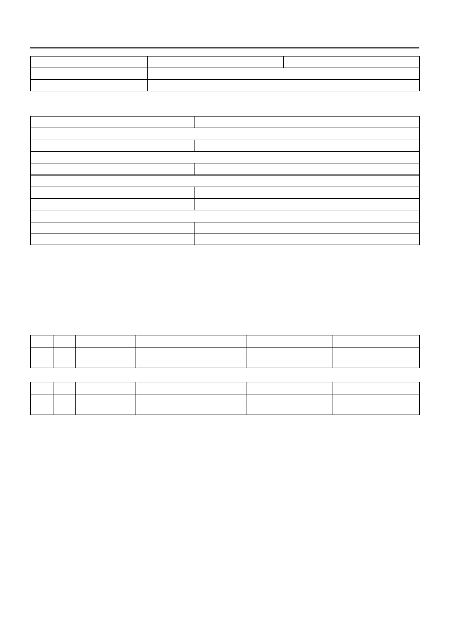
TYPICAL MALFUNCTION THRESHOLDS
Detection Criteria
Threshold
P2195, P2197 (A/F sensor signal stuck lean):
A/F sensor voltage
More than 3.8 V for 15 sec.
P2196, P2198 (A/F sensor signal stuck rich):
A/F sensor voltage
Less than 2.8 V for 15 sec.
P2195, P2197 (A/F sensor current (High side)):
Duration of the following condition
3 sec. or more
A/F sensor current
3.6 mA or more
P2196, P2198 (A/F sensor current (Low side)):
Duration of the following condition
3 sec. or more
A/F sensor current
Less than 1.4 mA
MONITOR RESULT
Refer to page
for detailed information.
The test value and test limit information are described as shown in the following table. Check the monitor
result and test values after performing the monitor drive pattern (refer to ”Confirmation Monitor”).
MID (Monitor Identification Data) is assigned to each emissions–related component.
TID (Test Identification Data) is assigned to each test value.
A/F sensor bank 1 sensor 1
MID
TID
Scaling
Description of Test Value
Minimum Test Limit
Maximum Test Limit
$01
$91
Multiply by 0.003906
(mA)
A/F current
Minimum test limit
Maximum test limit
A/F sensor bank 2 sensor 1
MID
TID
Scaling
Description of Test Value
Minimum Test Limit
Maximum Test Limit
$05
$91
Multiply by 0.003906
(mA)
A/F current
Minimum test limit
Maximum test limit
A23547
2
A1A–
MREL
HA2A
A1A+
ECM
22
30
B–W
E4
E7
E7
E7
BR
W–B
2
EFI Relay
A39 A/F Sensor
(Bank 2 Sensor 1)
J42
J/C
Engine Room R/B No. 2
W
1
14
F10
FL
Block
Battery
ED
(Shielded)
8
EB
3
2
HT
AF+
+B
B
E7
7
E04
2
IA4
5
L–R
G–R
2
G–B
2
B
1
B
1
4
BR
B–W
W–B
2F
A/F
1
1
1
2
Engine Room R/B and J/B
2D
2A
2H
2
6
EFI No. 1
EFI No. 2
2
2
W–B
A/F Relay
1
2
3
5
A
A
J2
J/C
G–R
15
IA5
1
IG4
(Shielded)
G
R
EC
E
E
C
C
C
J42
J/C
J5
J/C
J2
J/C
B
B
5
Engine
Room
R/B No. 2
R–W
R–W
R–W
R–W
A38 A/F Sensor
(Bank 1 Sensor 1)
+B
AF–
HT
AF+
AF–
1
3
2
4
1
3
2
4
R–W
L
31
E7
23
E7
E7
A2A+
A2A–
HA1A
B
R/B
–
DIAGNOSTICS
ENGINE
DI–389
583
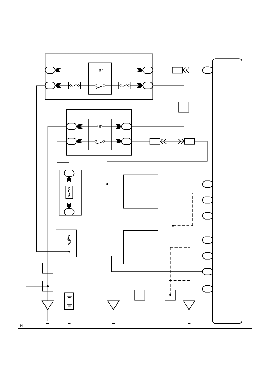
WIRING DIAGRAM
A23662
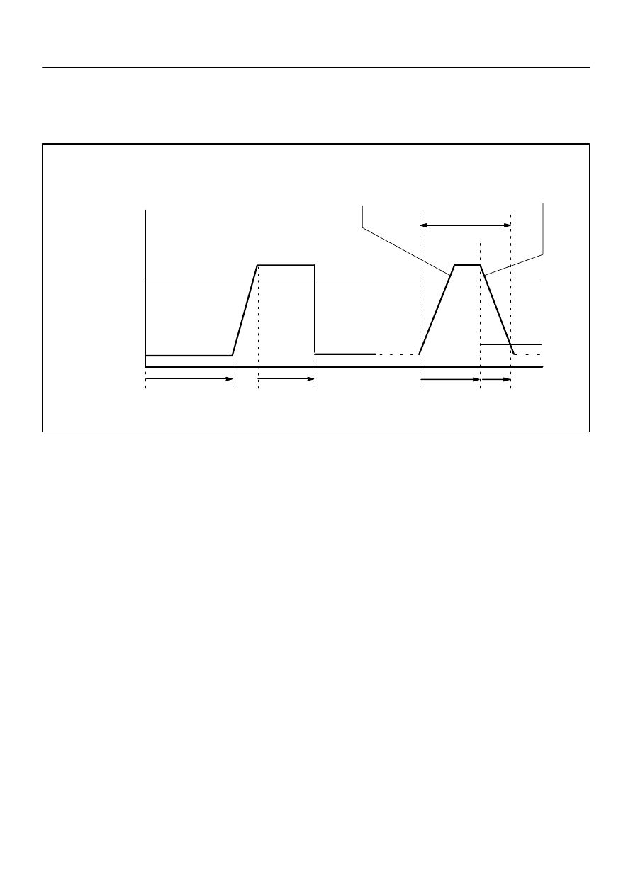
40 mph (64 km/h)
Idling
IG SW OFF
ECT:
75
C (167
F) or higher
Vehicle Speed
Warming up
(d)
(f)
10 minutes
or more
(g)
10 seconds
or more
4 seconds
or more
Time
At Least 3 times
(h)
(i)
(j)
Accelerator Pedal
Depressed
Accelerator Pedal
Released (Fuel–cut)
DI–390
–
DIAGNOSTICS
ENGINE
584
CONFIRMATION DRIVING PATTERN
HINT:
This confirmation driving pattern is used in steps 2, 4, 7, 17 and 21 of the following diagnostic troubleshooting
procedure when using a hand–held tester.
(a)
Connect the hand–held tester to DLC3.
(b)
Turn the ignition switch to ON and turn the tester ON.
(c)
Clear DTCs (see page
(d)
Start the engine, and warm it up until the ECT reaches 75
C (167
F) or higher.
(e)
On the hand–held tester, select the following menu items: DIAGNOSIS/ENHANCED OBD II/DATA
LIST/FC IDL.
(f)
Drive the vehicle at 40 mph (64 km/h) or more for at least 10 minutes.
(g)
Change the transmission to 2nd gear.
(h)
Drive the vehicle at proper vehicle speed to perform fuel–cut operation.
HINT:
Fuel–cut is performed under following conditions met:
Accelerator pedal fully released.
Engine speed 2,500 rpm or more (fuel injection returns at 1,000 rpm).
(i)
Accelerate the vehicle to 30 mph (48 km/h) or more by depressing the accelerator pedal for at least
10 seconds.
(j)
Soon after performing step (8) above, release the accelerator pedal for at least 4 seconds without de-
pressing the brake pedal, in order to execute fuel–cut control.
(k)
Stop the vehicle and allow the engine to idle for 10 seconds or more.
(l)
Allow the vehicle to decelerate until the vehicle speed declines to less than 6 mph (10 km/h).
(m)
Repeat steps from (8) through (10) above at least 3 times in one driving cycle.
HINT:
Completing all A/F sensor monitors are required to change the value in TEST RESULT.
CAUTION:
Strictly observe of posted speed limits, traffic laws, and road conditions when performing these
drive pattern.
Нет комментариевНе стесняйтесь поделиться с нами вашим ценным мнением.
Текст