Toyota Sequoia (2005). Manual — part 150
–
DIAGNOSTICS
ENGINE
DI–395
589
The ECM must establish a closed throttle valve position learning value to perform fuel cut. If the battery
terminal has been reconnected, the vehicle must be driven over 10 mph (16 km/h) to allow the ECM
to learn the closed throttle valve position.
When the vehicle is driven:
The output voltage of the A/F sensor may be below 0.56 V during fuel enrichment. For the vehicle, this
translates to a sudden increase in speed with the accelerator pedal fully depressed when trying to over-
take another vehicle. The A/F sensor is functioning normally.
The A/F sensor is a current output element; therefore, the current is converted into a voltage inside
the ECM. Measuring the voltage at the connectors of the A/F sensor or ECM will show a constant volt-
age result.
NG
Go to step 9.
OK
4
Perform confirmation driving pattern.
NEXT
5
Check whether DTC output recurs (DTC P2195, P2196, P2197 or P2198)
CHECK:
(a)
On the hand–held tester, select the following menu items: DIAGNOSIS / ENHANCED OBD II / DTC
INFO / PENDING CODES.
(b)
Read DTCs.
RESULT:
Display (DTC Output)
Proceed To
P2195, P2196, P2197 or P2198
A
No output
B
B
Go to step 5.
A
DI–396
–
DIAGNOSTICS
ENGINE
590
6
Replace air fuel ratio sensor.
NEXT
7
Perform confirmation driving pattern.
NEXT
8
Check whether DTC output recurs (DTC P2195, P2196, P2197 or P2198)
CHECK:
(a)
On the hand–held tester, select the following menu items: DIAGNOSIS / ENHANCED OBD II / DTC
INFO / PENDING CODES.
(b)
Read DTCs.
RESULT:
Display (DTC Output)
Proceed To
P2195, P2196, P2197 or P2198
A
No output
B
B
Go to step 5.
A
9
Confirm whether vehicle has run out of fuel in past.
NO
Check for intermittent problems
(See page
YES
DTC caused by running out of fuel.
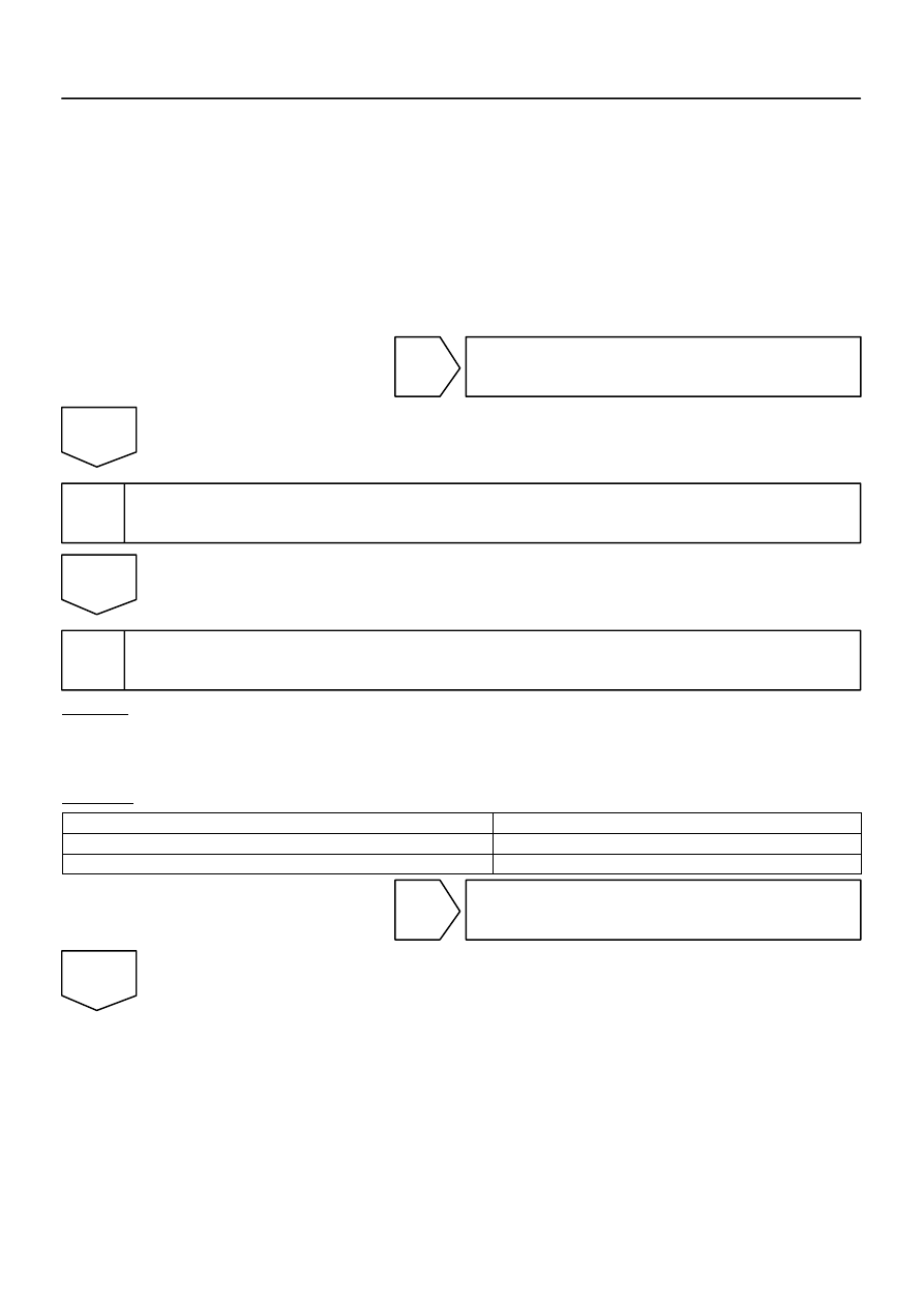
B17396
HT
+B
AF–
AF+
Sensor 1
A/F Sensor
Component Side:
Front View
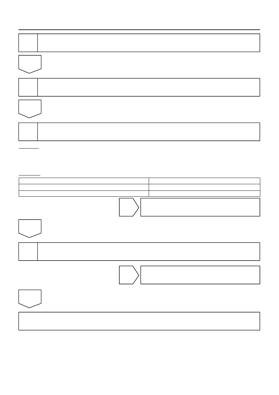
A19288
A/F Relay
–
DIAGNOSTICS
ENGINE
DI–397
591
10
Check resistance of air–fuel ratio (A/F) sensor heater.
PREPARATION:
Disconnect the air–fuel ratio (A/F) sensor connector.
CHECK:
Measure resistance between the terminals of the A/F sensor
connector.
OK:
Tester Connection
Specified Condition
HT (1) – +B (2)
Between 1.8
Ω
and 3.4
Ω
at 20
C (68
F)
HT (1) – AF– (4)
10 k
Ω
or higher
NG
Replace air–fuel ratio (A/F) sensor.
OK
11
Check A/F relay.
PREPARATION:
Remove the A/F relay from the engine room J/B.
CHECK:
Inspect the A/F relay.
OK:
Standard:
Terminal No.
Condition
Specified Condition
3 – 5
Always
10 K
Ω
or higher
3 – 5
Apply B+ between
terminals 1 and 2
Below 1
Ω
NG
Replace EFI relay.
OK
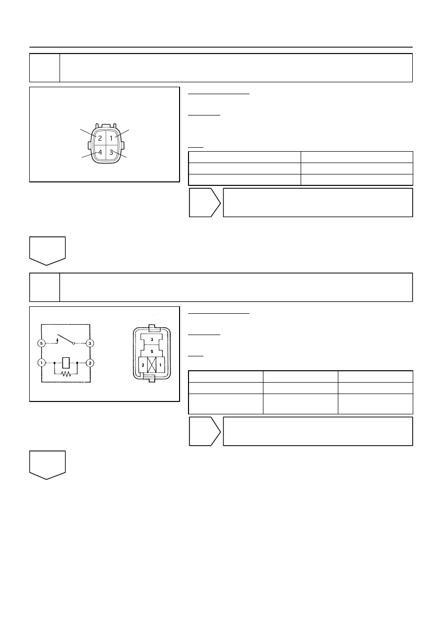
A23659
Wire Harness Side:
HT
A38
Sensor 1
A/F Sensor Connector
AF+
Front View
AF–
+B
A39
B17415
A55007
E7 ECM Connector
HA1A
A1A+
A1A–
A2A+
A2A–
HA2A
A23512
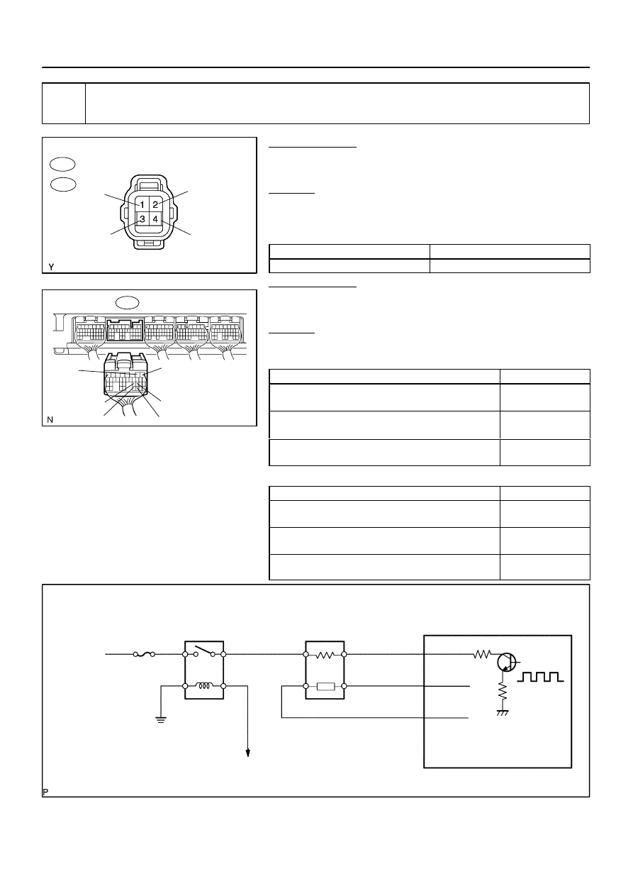
Reference (Bank 1 Sensor 1 System Drawing):
A/F Sensor
A/F Relay
Heater
Sensor
A1A+
HA1A
Duty
Control
ECM
From
Battery
A/F Heater
Fuse
A1A–
To EFI Relay
DI–398
–
DIAGNOSTICS
ENGINE
592
12
Check for open and short in harness and connector between ECM and A/F sen-
sor.
PREPARATION:
(a)
Disconnect the A38 or A39 A/F sensor connector.
(b)
Turn the ignition switch to ON.
CHECK:
(a)
Measure the voltage between the +B terminal of the A/F
sensor connector and body ground.
Standard:
Tester Connections
Specified Conditions
+B (2) – Body ground
Between 9 V and 14 V
PREPARATION:
(a)
Turn the ignition switch to OFF.
(b)
Disconnect the E7 ECM connector.
CHECK:
(a)
Check the resistance.
Standard (Check for open):
Tester Connections
Specified Conditions
HT (A38–1) – HA1A (E7–2)
HT (A39–1) – HA2A (E7–1)
Below 1
Ω
AF+ (A38–3) – A1A+ (E7–22)
AF+ (A39–3) – A2A+ (E7–23)
Below 1
Ω
AF– (A38–4) – A1A– (E7–30)
AF– (A39–4) – A2A– (E7–31)
Below 1
Ω
Standard (Check for short):
Tester Connections
Specified Conditions
HT (A38–1) or HA1A (E7–2) – Body ground
HT (A39–1) or HA2A (E7–1) – Body ground
10 k
Ω
or higher
AF+ (A38–3) or A1A+ (E7–22) – Body ground
AF+ (A39–3) or A2A+ (E7–23) – Body ground
10 k
Ω
or higher
AF– (A38–4) or A1A– (E7–30) – Body ground
AF– (A39–4) or A2A– (E7–31) – Body ground
10 k
Ω
or higher
Нет комментариевНе стесняйтесь поделиться с нами вашим ценным мнением.
Текст