Toyota Sequoia (2005). Manual — part 146

–
DIAGNOSTICS
ENGINE
DI–379
573
5
Check whether DTC
output recurs (DTC P2120, P2122, P2123, P2125, P2127,
P2128 or P2138)
PREPARATION:
(a)
Connect the hand–held tester to the DLC3.
(b)
Disconnect the battery terminals or remove the EFI No. 1 fuse and ETCS fuse (Clear DTCs).
(c)
Start the engine.
(d)
Drive the engine at idle for 15 seconds or more.
(e)
On the hand–held tester, select the following menu items: DIAGNOSIS / ENHANCED OBD II / DTC
INFO / PENDING CODES.
CHECK:
Read the DTC output.
RESULT:
Display (DTC Output)
Proceed To
P2120, P2122, P2123,P2125, P2127, P2128 or P2138
A
No output
B
B
System is OK.
A
Replace ECM (See page

DI–380
–
DIAGNOSTICS
ENGINE
574
DTC
P2121
Throttle/Pedal Position Sensor/Switch ”D”
Circuit Range/Performance
HINT:
This is repair procedure for the ”accelerator pedal position sensor”.
CIRCUIT DESCRIPTION
Refer to DTC P2120 on page
.
DTC No.
DTC Detecting Condition
Trouble Area
P2121
Conditions (a) and (b) continue for 0.5 seconds:
(a) Difference between VPA and VPA2 exceeds the threshold
(b) IDL is OFF
Accelerator pedal position sensor circuit
Accelerator pedal position sensor
ECM
MONITOR DESCRIPTION
The accelerator pedal position sensor is mounted on the accelerator pedal bracket. The accelerator pedal
position sensor has 2 sensor elements/signal outputs: VPA1 and VPA2. VPA1 is used to detect the actual
accelerator pedal angle (used for engine control) and VPA2 is used to detect malfunctions in VPA1. When
the difference between the voltage outputs of VPA1 and VPA2 deviates from the standard, the ECM con-
cludes the accelerator pedal position sensor has a malfunction. The ECM turns on the MIL and a DTC is
set.
FAIL SAFE
The accelerator pedal position sensor has two (main and sub) sensor circuits. If a malfunction occurs in ei-
ther of the sensor circuits, the ECM detects the abnormal signal voltage difference between the two sensor
circuits and switches to limp mode. In limp mode, the remaining circuit is used to calculate the accelerator
pedal opening to allow the vehicle to continue driving.
If both circuits malfunction, the ECM regards the opening angle of the accelerator pedal to be fully closed.
In this case, the throttle valve will remain closed as if the engine is idling.
If a ”pass” condition is detected and then the ignition switch is turned OFF, the fail–safe operation will stop
and the system will return to normal condition.
MONITOR STRATEGY
Related DTCs
P2121
Accelerator position sensor (rationality)
Required sensors/components
Accelerator position sensor
Frequency of operation
Continuous
Duration
0.5 sec.
MIL operation
Immediate
Sequence of operation
None
DID8H–01
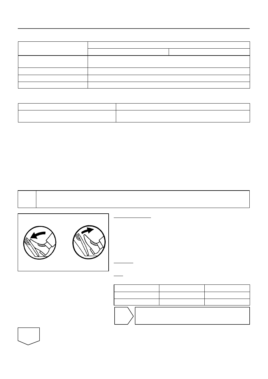
FI7052
Depressed
Released
–
DIAGNOSTICS
ENGINE
DI–381
575
TYPICAL ENABLING CONDITIONS
It
Specification
Item
Minimum
Maximum
The monitor will run whenever this DTC is
not present
See page
Either of the following conditions is met
Condition 1 or 2
1. Ignition switch
ON
2. Throttle control motor power
ON
TYPICAL MALFUNCTION THRESHOLDS
Detection Criteria
Threshold
Difference between VPA1 voltage (learned value) and VPA2
voltage (learned value)
Less than 0.4 V, or more than 1.2 V
WIRING DIAGRAM
Refer to DTC P2120 on page
.
INSPECTION PROCEDURE
HINT:
Read freeze frame data using
the hand−held tester
. Freeze frame data records the engine conditions when
a malfunction is detected. When troubleshooting, freeze frame data can help determine if the vehicle was
running or stopped, if the engine was warmed up or not, if the air–fuel ratio was lean or rich, as well as other
data from the time when a malfunction occurred.
1
Connect hand–held tester, and read the voltage for accelerator pedal position
sensor data.
PREPARATION:
(a)
Connect the hand–held tester to the DLC3.
(b)
Turn the ignition switch ON and push the hand–held tes-
ter main switch ON.
(c)
Enter the following menu: DIAGNOSIS / ENHANCED
OBD II / DATA LIST / ETCS / ACCEL POS #1 and ACCEL
POS #2.
CHECK:
Read the voltage for the accelerator pedal position sensor data.
OK:
Standard:
Accelerator pedal
ACCEL POS #1
ACCEL POS #2
Released
0.5 to 1.1 V
1.2 to 2.0 V
Depressed
2.6 to 4.5 V
3.4 to 5.3 V
OK
Replace ECM (See page
NG
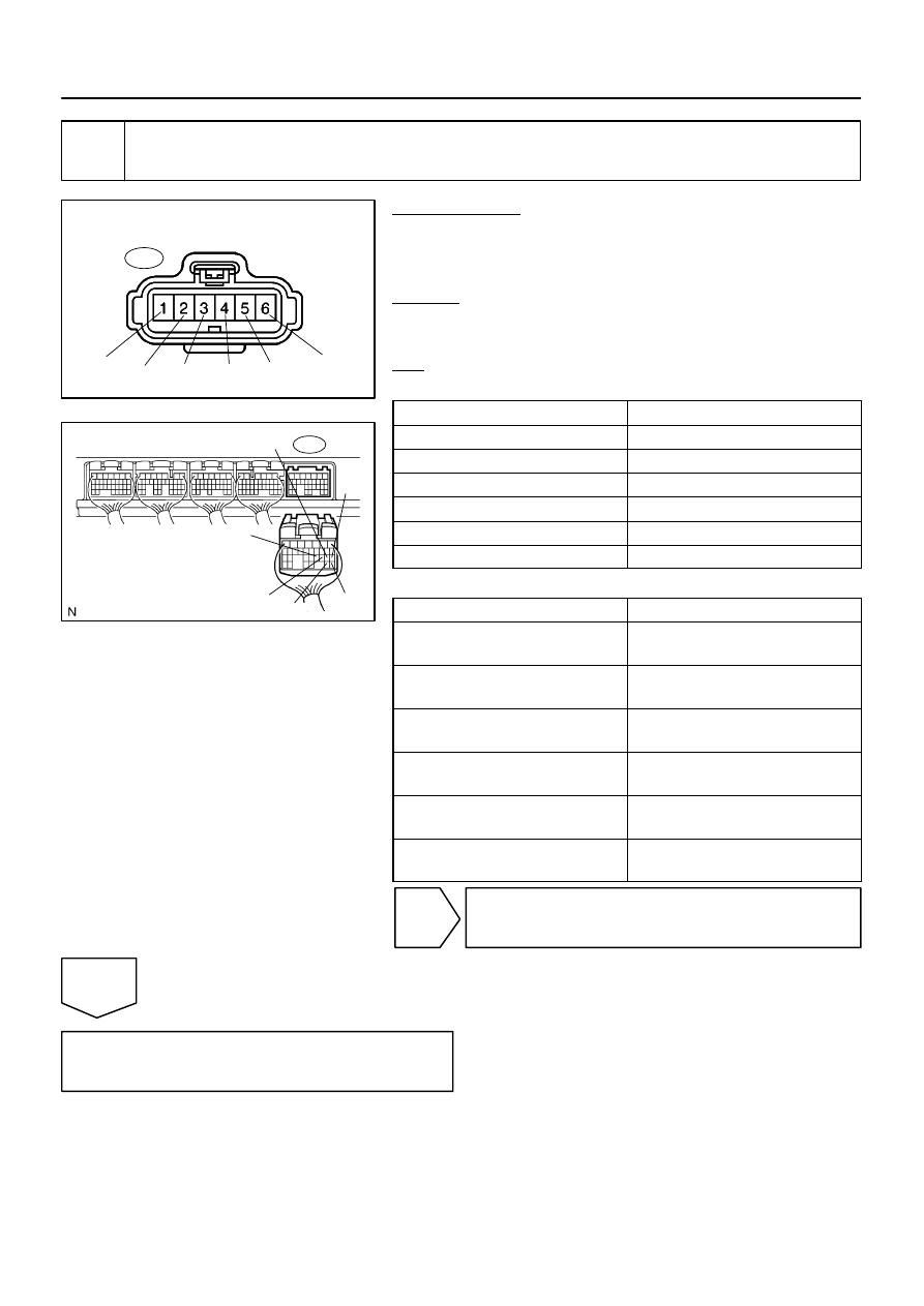
A21022
Wire Harness Side:
A37
Accelerator Pedal Position Sensor
VCP2
EPA2 VPA2 VCPA EPA
VPA
B17417
E4
VPA2
VCPA
VPA
EPA2
EPA
VCP2
DI–382
–
DIAGNOSTICS
ENGINE
576
2
Check for open and short in harness and connector between accelerator pedal
position sensor and ECM.
PREPARATION:
(a)
Disconnect the A37 accelerator pedal position sensor
connector.
(b)
Disconnect the E4 ECM connector.
CHECK:
Measure the resistance between the wire harness side connec-
tors.
OK:
Standard (Check for open):
Tester Connection
Specified Condition
VPA (A37–6) – VPA (E4–18)
Below 1
Ω
EPA (A37–5) – EPA (E4–20)
Below 1
Ω
VCPA (A37–4) – VCPA (E4–26)
Below 1
Ω
VPA2 (A37–3) – VPA2 (E4–19)
Below 1
Ω
EPA2 (A37–2) – EPA2 (E4–21)
Below 1
Ω
VCP2 (A37–1) – VCP2 (E4–27)
Below 1
Ω
Standard (Check for short):
Tester Connection
Specified Condition
VPA (A37–6) or VPA (E4–18) –
Body ground
10 k
Ω
or higher
EPA (A37–5) or EPA (E4–20) –
Body ground
10 k
Ω
or higher
VCPA (A37–4) or VCPA (E4–26) –
Body ground
10 k
Ω
or higher
VPA2 (A37–3) or VPA2 (E4–19) –
Body ground
10 k
Ω
or higher
EPA2 (A37–2) or EPA2 (E4–21) –
Body ground
10 k
Ω
or higher
VCP2 (A37–1) or VCP2 (E4–27) –
Body ground
10 k
Ω
or higher
NG
Repair or replace harness or connector.
OK
Replace accelerator pedal pedal assembly.
Нет комментариевНе стесняйтесь поделиться с нами вашим ценным мнением.
Текст