Toyota Sequoia (2005). Manual — part 155

–
DIAGNOSTICS
ENGINE
DI–415
609
4. Vacuum introduction and leak
–
Next sequence is run if both of following
conditions set
Condition 1 and 2
1. Vacuum introduction time
–
15 min.
2. FTP
FTP was saturated
5. Purge VSV stuck closed check
–
Next sequence is run if following condition
set
–
FTP change for 10 sec. after purge VSV
ON (open)
2.25 mmHg (0.3 kPa)
–
6. Second reference pressure measure-
ment
–
Next sequence is run if all of following
conditions set
Condition 1, 2, 3 and 4
1. FTP when 4 sec. after reference pres-
sure measurement
–
–7.5 mmHg (–1 kPa)
2. Reference pressure
–36.38 to –7.93 mmHg (–4.85 to –1.057 kPa)
3. Reference pressure
Saturated
4. Reference pressure difference between
first and second
–
5.25 mmHg (0.7 kPa)
7. Leak check
–
Next sequence is run if following condition
set
–
FTP when vacuum introduction was com-
plete
–
Second reference pressure
8. Atmospheric pressure
–
Monitor is complete if following
–
Atmospheric pressure difference between
sequence 1 and 8
–
2.25 mmHg (0.3 kPa)
TYPICAL MALFUNCTION THRESHOLDS
Detection Criteria
Threshold
Following values are when atmospheric pressure is 760
mmHg (100 kPa)
–
One of the following conditions set
Condition 1, 2, 3, 4 or 5
1. FTP when 4 sec. after reference pressure measurement
began
–7.5 mmHg (–1 kPa) or more
2. Reference pressure
–36.38 mmHg (–4.85 kPa) or less
3. Reference pressure
–7.93 mmHg (–1.057 kPa) or more
4. Reference pressure
Not saturated
5. Reference pressure difference between first and second
More than 5.25 mmHg (0.7 kPa)
MONITOR RESULT (MODE 06 DATA)
Refer to page
for detailed information on Monitor Result.
INSPECTION PROCEDURE
Refer to the EVAP Inspection Procedure (see page

DI–416
–
DIAGNOSTICS
ENGINE
610
DTC
P2419
Evaporate Emission System Switching
Valve Control Circuit Low
DTC
P2420
Evaporate Emission System Switching
Valve Control Circuit High
DTC SUMMARY
DTCs
Monitoring Items
Malfunction Detection Conditions
Trouble Areas
Detection
Timings
Detection
Logic
P2419
Vent valve stuck closed
Vacuum pump creates negative pressure
through 0.02 inch orifice and EVAP system
pressure measured to determine leak pres-
sure standard.
If system pressure higher than –1.06 kPa
(–7.95 mmHg)* 4 seconds after vacuum
pump turned ON, ECM determines that
vent valve stuck closed.
Pump module
Connector/Wire harness
(Pump module – ECM)
ECM
While
ignition
switch
OFF
2 trip
P2420
Vent valve stuck open (vent)
Vacuum pump creates negative pressure
through 0.02 inch orifice and EVAP system
pressure measured to determine leak pres-
sure standard. 0.02 inch leak pressure
standard is measured at the start and at the
end of the leak check.
If system pressure does not increase by
more than 0.3 kPa (2.25 mmHg) within 10
seconds when vent valve turned ON, ECM
determines that vent valve stuck close.
Pump module
Connector/Wire harness
(Pump module – ECM)
ECM
While
ignition
switch
OFF
2 trip
*: The threshold value varies according to the atmospheric pressure measured in operation A. The value
described above is based on an atmospheric pressure of 100 kPa (750.1 mmHg): absolute pressure.
HINT:
The vent valve is built into the pump module.
CIRCUIT DESCRIPTION
The circuit description can be found in the EVAP (Evaporative Emission) Inspection Procedure (see page
DIDFW–01
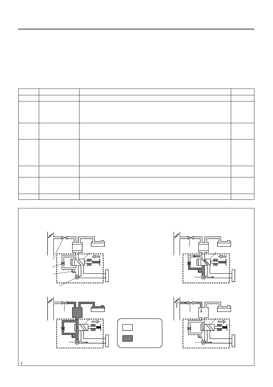
A23480
Fuel Tank
Canister
Vacuum Pump: OFF
Pressure Sensor
0.02 Inch Orifice
Pump Module
Operation A: Atmospheric Pressure Measurement
Vent Valve: OFF (vent)
Operation D: Purge VSV monitor
Operation B: 0.02 Inch Leak Pressure Measurement
Negative
Pressure
Atmospheric
Pressure
Operation C: EVAP Leak Check
Air Filter
Purge VSV: OFF
OFF (vent)
ON
OFF
OFF
ON
ON (closed)
ON
ON
ON (closed)
–
DIAGNOSTICS
ENGINE
DI–417
611
MONITOR DESCRIPTION
5 hours* after the ignition switch is turned OFF, the electric vacuum pump creates negative pressure (vacu-
um) in the EVAP (Evaporative Emission) system. The ECM monitors for leaks and actuator malfunctions
based on the EVAP pressure.
HINT:
*: If the engine coolant temperature is not below 35
C (95
F) 5 hours after the ignition switch is turned off,
the monitor check starts 2 hours later. If it is still not below 35
C (95
F) 7 hours after the ignition switch is
turned off, the monitor check starts 2.5 hours later.
Sequence
Operations
Descriptions
Duration
–
ECM activation
Activated by soak timer, 5 hours (7 or 9.5 hours) after ignition switch turned to OFF.
–
A
Atmospheric pressure
measurement
Vent valve turned OFF (vent) and EVAP system pressure measured by ECM in order to
register atmospheric pressure.
If EVAP pressure is not between 70 kPa and 110 kPa (525 mmHg and 825 mmHg), ECM
cancels EVAP system monitor.
10 seconds
B
First 0.02 inch leak
pressure measure-
ment
In order to determine 0.02 inch leak pressure standard, vacuum pump creates negative pres-
sure (vacuum) through 0.02 inch orifice and them ECM checks if vacuum pump and vent
valve operate normally.
60 seconds
C
EVAP system pres-
sure measurement
Vent valve turned ON (closed) to shut EVAP system.
Negative pressure (vacuum) created in EVAP system, and EVAP system pressure then
measured.
Write down the measured value as it will be used in the leak check.
If EVAP pressure does not stabilize within 15 minutes, ECM cancels EVAP system monitor.
15 minutes*
D
Purge VSV monitor
Purge VSV opened and then EVAP system pressure measured by ECM.
Large increase indicates normal.
10 seconds
E
Second 0.02 inch leak
pressure measure-
ment
Leak check is performed after second 0.02 inch leak pressure standard is measured.
If stabilized system pressure higher than second 0.02 inch leak pressure standard, ECM
determines that EVAP system leaking.
60 seconds
F
Final check
Atmospheric pressure measured and then monitoring result recorded by ECM.
–
* If only a small amount of fuel is in the fuel tank, it takes longer for the EVAP pressure to stabilize.
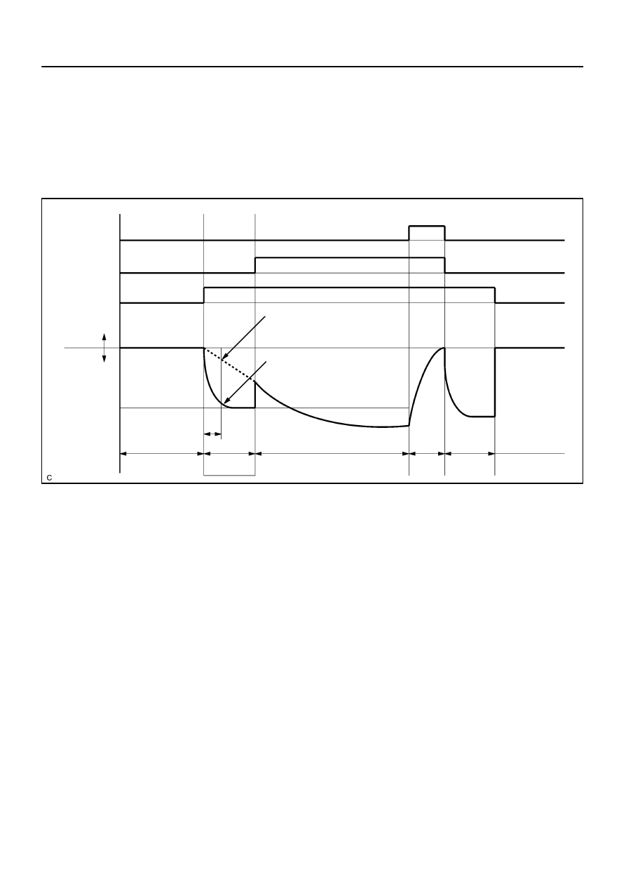
A23665
Purge VSV
Vent Valve
Vacuum Pump
EVAP Pressure
Positive
Leak Pressure
sec
Negative
ON
ON
Sequence
Time
A
10
sec
60
Within 15 minutes
sec
ON
First 0.02 inch
B
C
D
EVAP Pressure when Vent Valve Stuck ON (closed):
OK
Malfunction
ON: Open
OFF: Closed
OFF: Vent
ON: Closed
10
Standard
sec
60
E
sec
4
DI–418
–
DIAGNOSTICS
ENGINE
612
(a)
P2419: Vent valve stuck closed
In operation B, the vacuum pump creates negative pressure (a vacuum) through the 0.02 inch orifice. The
EVAP (Evaporative Emission) system pressure is then measured by the ECM, using the pressure sensor,
to determine the 0.02 inch leak pressure standard. If the pressure exceeds –1.06 kPa (–7.95 mmHg)* 4 se-
conds after the vacuum pump is turned ON, the ECM interprets this as the vent valve being stuck closed.
The ECM illuminates the MIL and sets the DTC (2 trip detection logic).
*: The threshold varies according to the atmospheric pressure measured in operation A. The value described
above is based on an atmospheric pressure of 100 kPa (750.1 mmHg): absolute pressure.
Нет комментариевНе стесняйтесь поделиться с нами вашим ценным мнением.
Текст