Toyota Sequoia (2005). Manual — part 156
A23666
Purge VSV
Vent Valve
Vacuum Pump
EVAP Pressure
Positive
Leak Pressure
sec
Negative
ON
ON
Sequence
Time
A
10
sec
60
Within 15 minutes
ON
First 0.02 inch
B
C
D
EVAP Pressure when Vent Valve Stuck OFF (vent):
OK
Malfunction
ON: Open
OFF: Closed
OFF: Vent
ON: Closed
10
Standard
sec
60
E
–
DIAGNOSTICS
ENGINE
DI–419
613
(b)
P2420: Vent valve stuck open (vent)
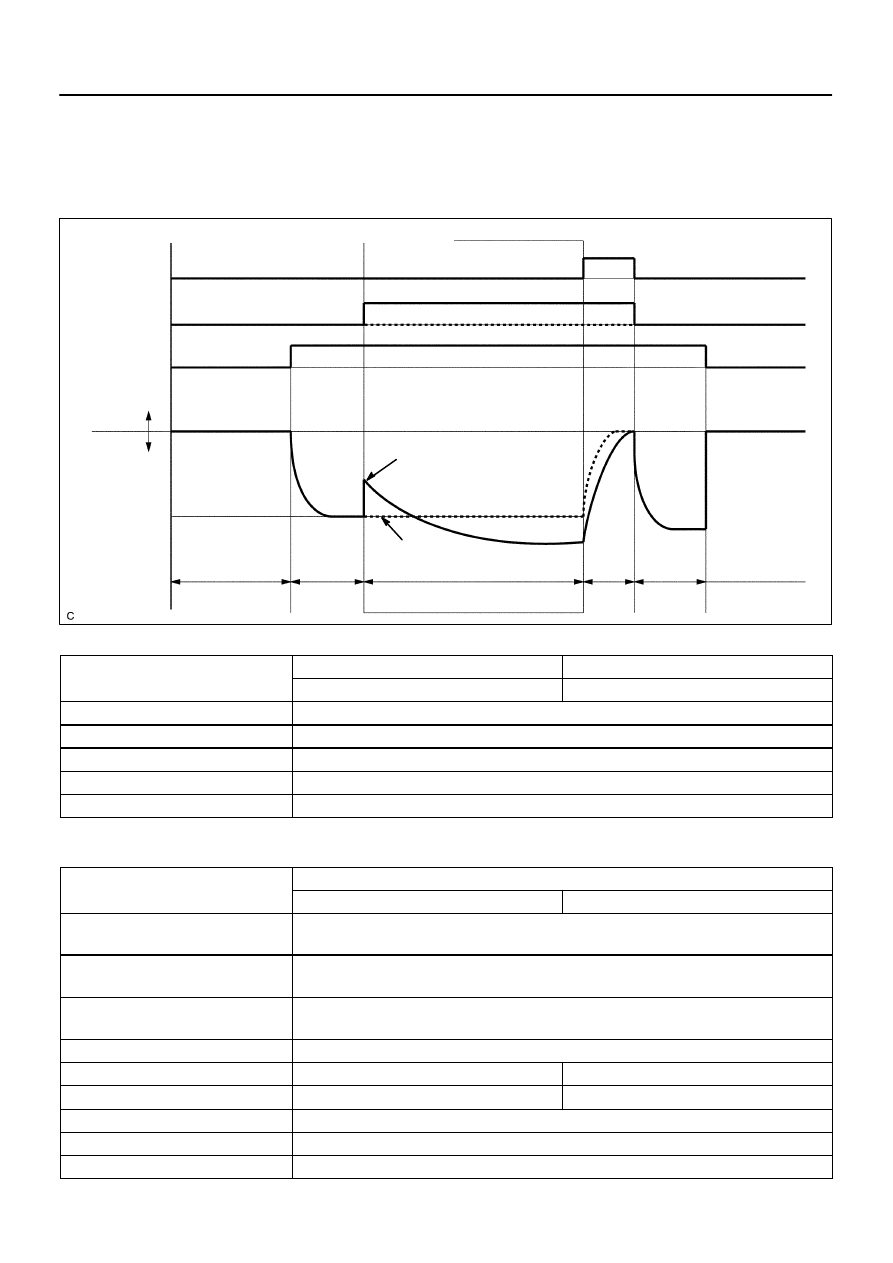
In operation C, the vent valve turns ON (closes) and the EVAP (Evaporative Emission) system pressure is
then measured by the ECM, using the pressure sensor, to conduct an EVAP leak check. If the pressure does
not increase when the vent valve is open, the ECM interprets this as the vent valve being stuck open. The
ECM illuminates the MIL and sets the DTC.
MONITOR STRATEGY
R l t d DTC
P2419
Vent valve stuck open
Related DTCs
P2420
Vent valve stuck closed
Required sensors/components
Vent valve
Frequency of operation
Once per driving cycle
Duration
8 sec. (P2419), 10 sec. (P2420)
MIL operation
2 driving cycles
Sequence of operation
None
TYPICAL ENABLING CONDITIONS
It
Specification
Item
Minimum
Maximum
The monitor will run whenever these
DTCs are not present
See page
Following values are when atmospheric is
760 mmHg (100 kPa)
–
EVAP key–off monitor runs when all of the
following conditions met:
–
Atmospheric pressure
525 to 825 mmHg (70 to 110 kPa)
Battery voltage
10.5 V
–
Vehicle speed
–
4 km/h (2.5 mph)
Ignition switch
OFF
Engine condition
Not running
Time after engine stopped
5 hours

DI–420
–
DIAGNOSTICS
ENGINE
614
FTP sensor malfunction (P0450, P0452,
P0453)
Not detected
Purge VSV
Not operated by scan tool
Vent valve
Not operated by scan tool
Leak detection pump
Not operated by scan tool
Both of the following conditions are met
before IG switch OFF
Condition 1 and 2
1. Duration that vehicle is driven
5 min.
–
2. Purge flow
Executed
ECT
4.4 to 35
°
C (40 to 95
°
F)
IAT
4.4 to 35
°
C (40 to 95
°
F)
Example of re–start time
–
First time
7 hours
Second time
9 hours and 30 min.
Key–off monitor sequence
1 to 8
1. Atmospheric pressure
–
Next sequence is run if following condition
set
–
Atmospheric pressure change for 10 sec.
–
2.25 mmHg (0.3 kPa) for 1 sec.
2. First reference pressure
–
Next sequence is run if all of following
conditions set
Condition 1, 2 and 3
1. FTP when 4 sec. after reference pres-
sure measurement
–
–7.5 mmHg (–1 kPa)
2. Reference pressure
–36.38 to –7.93 mmHg (–4.85 to –1.057 kPa)
3. Reference pressure
Saturated
3. Vent valve stuck closed check
–
Next sequence is run if following condition
set
–
FTP change for 10 sec. after vent valve
ON (closed)
2.25 mmHg (0.3 kPa)
–
4. Vacuum introduction and leak
–
Next sequence is run if both of following
conditions set
Condition 1 and 2
1. Vacuum introduction time
–
15 min.
2. FTP
FTP was saturated
5. Purge VSV stuck closed check
–
Next sequence is run if following condition
set
–
FTP change for 10 sec. after purge VSV
ON (open)
2.25 mmHg (0.3 kPa)
–
6. Second reference pressure measure-
ment
–
Next sequence is run if all of following
conditions set
Condition 1, 2, 3 and 4
1. FTP when 4 sec. after reference pres-
sure measurement
–
–7.5 mmHg (–1 kPa)
2. Reference pressure
–36.38 to –7.93 mmHg (–4.85 to –1.057 kPa)

–
DIAGNOSTICS
ENGINE
DI–421
615
3. Reference pressure
Saturated
4. Reference pressure difference between
first and second
–
5.25 mmHg (0.7 kPa)
7. Leak check
–
Next sequence is run if following condition
set
–
FTP when vacuum introduction was com-
plete
–
Second reference pressure
8. Atmospheric pressure
–
Monitor is complete if following
–
Atmospheric pressure difference between
sequence 1 and 8
–
2.25 mmHg (0.3 kPa)
TYPICAL MALFUNCTION THRESHOLDS
Detection Criteria
Threshold
Vent valve stuck open:
Following valuers are when atmospheric pressure is 760
mmHg (100 kPa)
–
One of the following conditions set
Condition 1, 2, 3, 4 or 5
1. FTP when 4 sec. after reference pressure measurement
began
–7.5 mmHg (–1 kPa) or more
2. Reference pressure
–36.38 mmHg (–4.85 kPa) or less
3. Reference pressure
–7.93 mmHg (–1.057 kPa) or more
4. Reference pressure
Not saturated
5. Reference pressure difference between first and second
More than 5.25 mmHg (0.7 kPa)
Vent valve stuck closed:
FTP change for 10 sec. after vent valve opened
Less than 2.25 mmHg (0.3 kPa)
MONITOR RESULT (MODE 06 DATA)
Refer to page
for detailed information on Monitor Result.
INSPECTION PROCEDURE
Refer to the EVAP Inspection Procedure (see page

A20311
Pressure
Sensor
ECM
VC
AIP
E2
VC
PIM
E2
DI–422
–
DIAGNOSTICS
ENGINE
616
DTC
P2430
Secondary Air Injection System Air Flow/
Pressure Sensor Circuit Bank 1
DTC
P2431
Secondary Air Injection System Air Flow/Pressure
Sensor Circuit Range/Performance Bank 1
DTC
P2432
Secondary Air Injection System Air Flow/
Pressure Sensor Circuit Low Bank 1
DTC
P2433
Secondary Air Injection System Air Flow/
Pressure Sensor Circuit High Bank 1
CIRCUIT DESCRIPTION
Refer to DTC P412 on page
DTC No.
DTC Detecting Condition
Trouble Area
P2430
While the engine is running, voltage output of the pressure
sensor indicates 0.1V or less, or indicates 4.8V or more.
(1 trip detection logic)
P2431
The pressure sensor indicates less than 45 kPa (338 mHg), or
more than 135 kPa (1013 mHg).
(1 trip detection logic)
Pressure sensor
O
h t i
i
it
P2432
While the engine is running, voltage output of pressure sensor
remains below 0.1 V.
(1 trip detection logic)
Open or short in pressure sensor circuit
ECM
P2433
While the engine is running, voltage output of the pressure
sensor remains above 4.8 V.
(1 trip detection logic)
MONITOR DESCRIPTION
The ECM observes the pressure in the secondary air passage
using the pressure sensor located on the air switching valve in
the secondary air injection system.
If there is a defect in the sensor or the sensor circuit, the voltage
level will deviate from the normal operating range, the ECM in-
terprets this deviation as a defect in the pressure sensor circuit
and sets a DTC.
DIDMT–01
Нет комментариевНе стесняйтесь поделиться с нами вашим ценным мнением.
Текст