Toyota Sequoia (2005). Manual — part 153
B17396
HT
+B
AF–
AF+
Sensor 1
A/F Sensor
Component Side:
Front View
A19288
–
DIAGNOSTICS
ENGINE
DI–407
601
HINT:
Read freeze frame data using a hand–held tester. Freeze frame data record the engine condition when mal-
functions are detected. When troubleshooting, freeze frame data can help determine if the vehicle was mov-
ing or stationary, if the engine was warmed up or not, if the air–fuel ratio was lean or rich, and other data,
from the time the malfunction occurred.
1
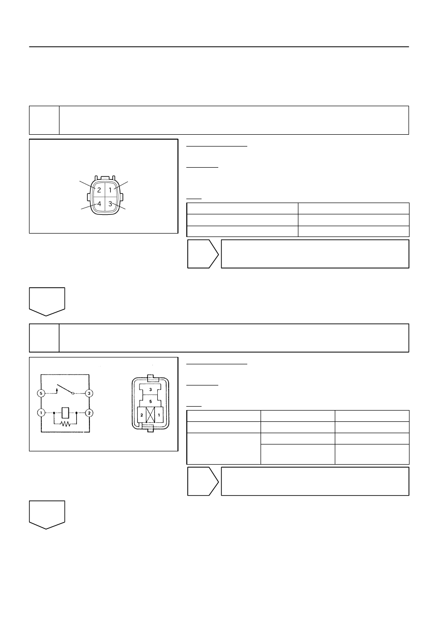
Check resistance of air–fuel ratio (A/F) sensor heater.
PREPARATION:
Disconnect the air–fuel ratio (A/F) sensor connector.
CHECK:
Measure resistance between the terminals of the A/F sensor
connector.
OK:
Tester Connection
Specified Condition
HT (1) – +B (2)
Between 1.8
Ω
and 3.4
Ω
at 20
C (68
F)
HT (1) – AF– (4)
10 k
Ω
or higher
NG
Replace air–fuel ratio (A/F) sensor.
OK
2
Check A/F relay.
PREPARATION:
Remove the A/F relay from the engine room J/B.
CHECK:
Inspect the A/F relay.
OK:
Terminal No.
Condition
Specified Condition
1 – 2
Constant
Continuity
Usually
No Continuity
3 – 5
Apply B+ between
terminals 1 and 2
Continuity
NG
Replace EFI relay.
OK
A23659
Wire Harness Side:
HT
A38
Sensor 1
A/F Sensor Connector
AF+
Front View
AF–
+B
A39
B17415
A55007
E7
ECM Connector
HA1A
A1A+
A1A–
A2A+
A2A–
HA2A
A23512
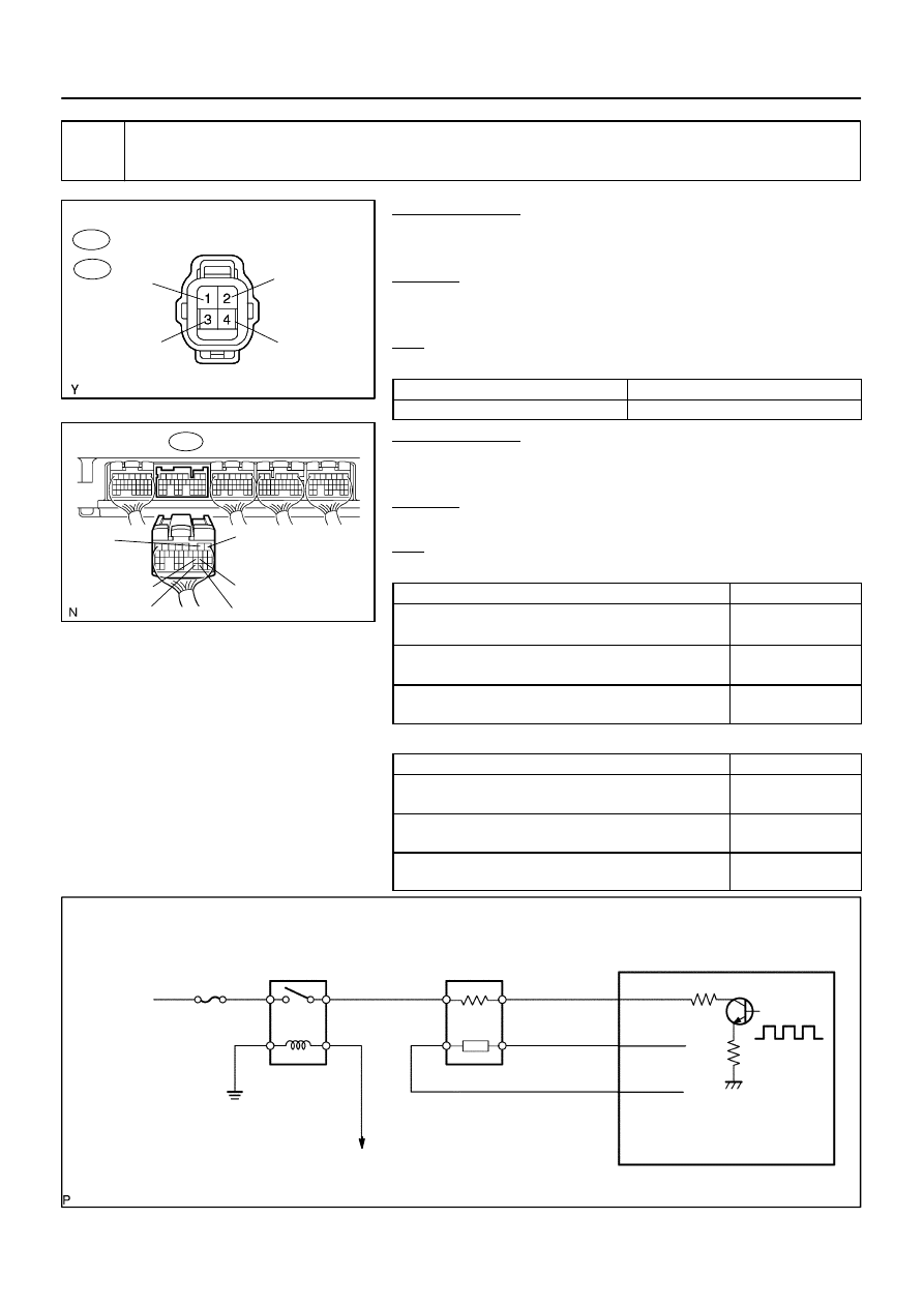
Reference (Bank 1 Sensor 1 System Drawing):
A/F Sensor
A/F Relay
Heater
Sensor
A1A+
HA1A
Duty
Control
ECM
From
Battery
A/F Heater
Fuse
A1A–
To EFI Relay
DI–408
–
DIAGNOSTICS
ENGINE
602
3
Check for open and short in harness and connector between ECM and A/F sen-
sor.
PREPARATION:
(a)
Disconnect the A38 or A39 A/F sensor connector.
(b)
Turn the ignition switch to ON.
CHECK:
(a)
Measure the voltage between the +B terminal of the A/F
sensor connector and body ground.
OK:
Standard:
Tester Connections
Specified Conditions
+B (2) – Body ground
Between 9 V and 14 V
PREPARATION:
(a)
Turn the ignition switch to OFF.
(b)
Disconnect the E7 ECM connector.
CHECK:
(a)
Check the resistance.
OK:
Standard (Check for open):
Tester Connections
Specified Conditions
HT (A38–1) – HA1A (E7–2)
HT (A39–1) – HA2A (E7–1)
Below 1
Ω
AF+ (A38–3) – A1A+ (E7–22)
AF+ (A39–3) – A2A+ (E7–23)
Below 1
Ω
AF– (A38–4) – A1A– (E7–30)
AF– (A39–4) – A2A– (E7–31)
Below 1
Ω
Standard (Check for short):
Tester Connections
Specified Conditions
HT (A38–1) or HA1A (E7–2) – Body ground
HT (A39–1) or HA2A (E7–1) – Body ground
10 k
Ω
or higher
AF+ (A38–3) or A1A+ (E7–22) – Body ground
AF+ (A39–3) or A2A+ (E7–23) – Body ground
10 k
Ω
or higher
AF– (A38–4) or A1A– (E7–30) – Body ground
AF– (A39–4) or A2A– (E7–31) – Body ground
10 k
Ω
or higher

–
DIAGNOSTICS
ENGINE
DI–409
603
NG
Replace or replace harness or connector.
OK
Replace ECM (See page

DI–410
–
DIAGNOSTICS
ENGINE
604
DTC
P2401
Evaporative Emission System Leak Detec-
tion Pump Control Circuit Low
DTC
P2402
Evaporative Emission System Leak Detec-
tion Pump Control Circuit High
DTC SUMMARY
DTCs
Monitoring Items
Malfunction Detection Conditions
Trouble Areas
Detection
Timings
Detection
Logic
P2401
Vacuum pump stuck OFF
Vacuum pump creates negative pressure
through 0.02 inch orifice, and EVAP system
pressure measured to determine leak pres-
sure standard. 0.02 inch leak pressure
standard is measured at the start and at the
end of the leak check.
If system pressure higher than –1.06 kPa
(–7.93 mmHg)*, or lower than –4.85 kPa
(–36.38 mmHg)*, ECM determines that
vacuum pump stuck OFF.
Pump module
Connector/Wire harness
(Pump module – ECM)
ECM
While
ignition
switch
OFF
2 trip
P2402
Vacuum pump stuck ON
Vacuum pump creates negative pressure
through 0.02 inch orifice, and EVAP system
pressure measured to determine leak pres-
sure standard.
If system pressure higher than –1.06 kPa
(–7.93 mmHg)*, or lower than –4.85 kPa
(–36.38 mmHg)*, ECM determines that
vacuum pump stuck ON.
Pump module
Connector/Wire harness
(Pump module – ECM)
ECM
While
ignition
switch
OFF
2 trip
*: The threshold values vary according to the atmospheric pressure measured in operation A. The values
described in the table above are based on an atmospheric pressure of 100 kPa (750.1 mmHg).
HINT:
The vacuum pump is built into the pump module.
CIRCUIT DESCRIPTION
The circuit description can be found in the EVAP (Evaporative Emission) Inspection Procedure (see page
DIDFV–01
Нет комментариевНе стесняйтесь поделиться с нами вашим ценным мнением.
Текст