Toyota Sequoia (2005). Manual — part 619
I28483
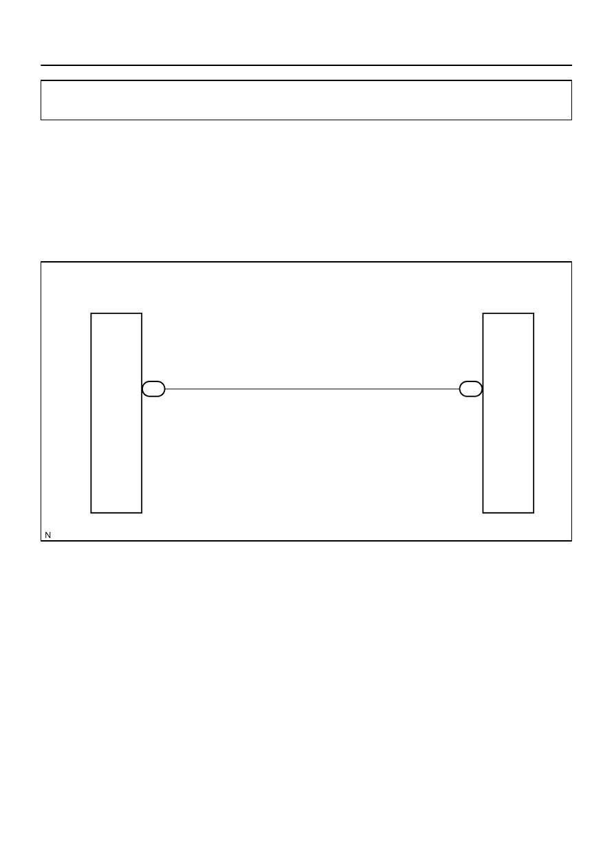
Radio and Navigation Assy
R–W
1
7
R28
MUTE
MUTE
Stereo Component
Amplifier Assy
S10
–
DIAGNOSTICS
NAVIGATION SYSTEM
DI–2271
2465
Amplifier mute signal circuit
CIRCUIT DESCRIPTION
This circuit sends a signal to the stereo component amplifier to mute noise. Because of that, the noise pro-
duced by changing the sound source ceases.
If there is an open in the circuit, noise can be heard from the speakers when changing the sound source.
If there is a short in the circuit, even though the stereo component amplifier assy is normal, no sound or only
an extremely small sound can be produced.
WIRING DIAGRAM
DIDDI–01
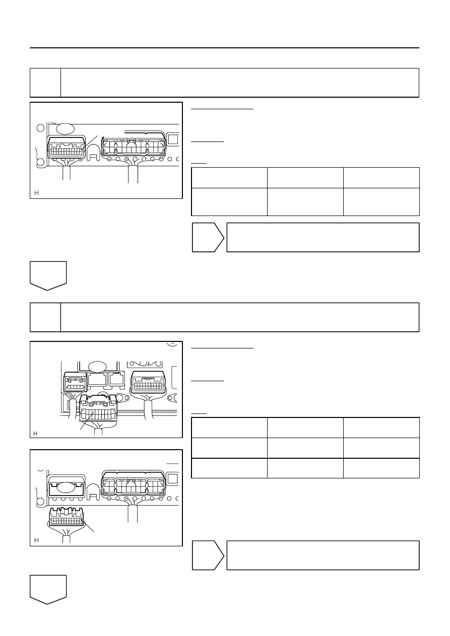
I28755
Stereo Component Amplifier Assy
Wire Harness View:
MUTE
S10
I28292
MUTE
Radio and Navigation Assy
Wire Harness View:
R28
I28752
Stereo Component Amplifier Assy
Wire Harness View:
MUTE
S10
DI–2272
–
DIAGNOSTICS
NAVIGATION SYSTEM
2466
INSPECTION PROCEDURE
1
Inspect stereo component amplifier assy.
PREPARATION:
Make sure that the stereo component amplifier assy connector
is connected.
CHECK:
Measure the voltage according to the value in the table below.
OK:
Symbol
(Tester connection)
Condition
Specification
MUTE (S10–1) –
Body ground
Turn ignition switch to
ACC, Audio system is
playing
→
Changing mode
Above 3.5 V
→
Below 1 V
OK
Proceed to next circuit inspection shown in
problem symptoms table (See page
NG
2
Check harness and connector (Radio and navigation assy – stereo component
amplifier assy).
PREPARATION:
Disconnect the radio and navigation assy and stereo compo-
nent amplifier assy connectors.
CHECK:
Measure the resistance according to the values in the table be-
low.
OK:
Symbol
(Tester connection)
Condition
Specified condition
MUTE (R28–7) –
MUTE (S10–1)
Always
Below 1
Ω
MUTE (R28–7) –
Body ground
Always
10 k
Ω
or higher
NG
Repair or replace harness or connector.
OK
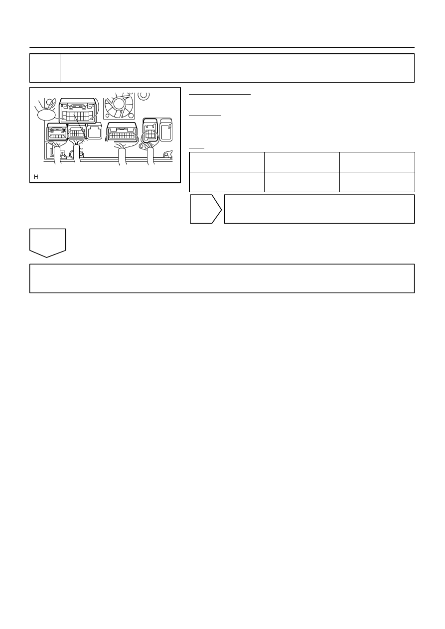
I28746
Wire Harness View:
R28
MUTE
–
DIAGNOSTICS
NAVIGATION SYSTEM
DI–2273
2467
3
Inspect radio and navigation assy.
PREPARATION:
Reconnect the radio and navigation assy connector.
CHECK:
Measure the voltage according to the value(s) in the table be-
low.
OK:
Symbol
(Tester connection)
Condition
Specified condition
MUTE (R28–7) –
Body ground
Ignition switch ON
Above 3.5 V
OK
Replace stereo component amplifier assy.
NG
Replace radio and navigation assy.
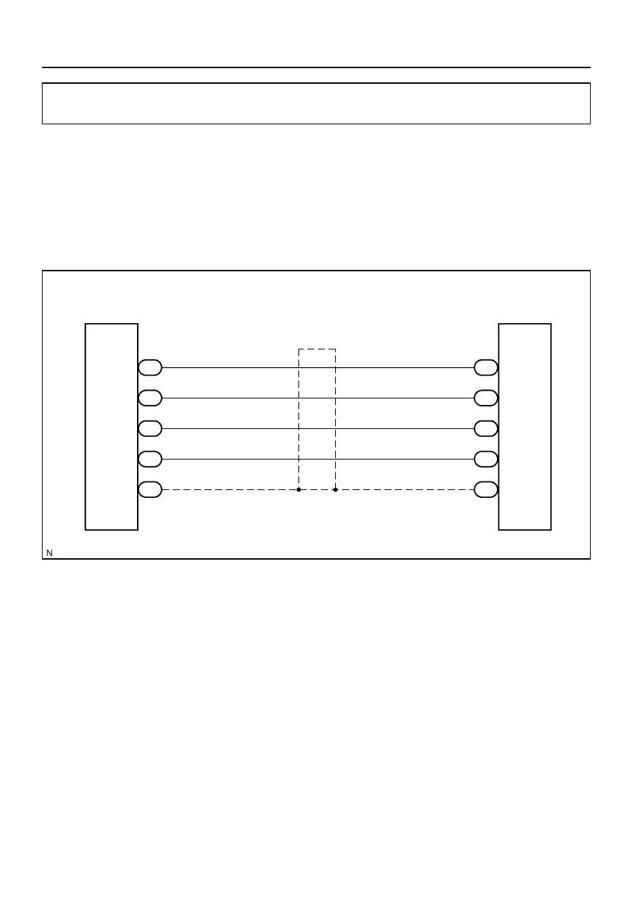
I28484
W
Radio and
Navigation Assy
G
4
2
9
8
R
B
R30 L+
L–
Stereo Component
Amplifier Assy
R+
R–
SLD
19
18
10
3
S10
5
(Shielded)
L+
L–
R+
R–
S10
S10
S10
S10
6
SGND
R30
R30
R30
R30
DI–2274
–
DIAGNOSTICS
NAVIGATION SYSTEM
2468
Amplifier sound signal circuit
CIRCUIT DESCRIPTION
The radio receiver assy sends a sound signal to the stereo component amplifier assy through this circuit.
The sound signal that has been sent is amplified by the stereo component amplifier assy, and then sent to
the speakers.
If there is an open or short in the circuit, sound cannot be heard from the speakers even if there is no malfunc-
tion in the stereo component amplifier assy or the speakers.
WIRING DIAGRAM
DIDDJ–01
Нет комментариевНе стесняйтесь поделиться с нами вашим ценным мнением.
Текст