Toyota Sequoia (2005). Manual — part 620
I28292
L+
R–
L–
R+
R30
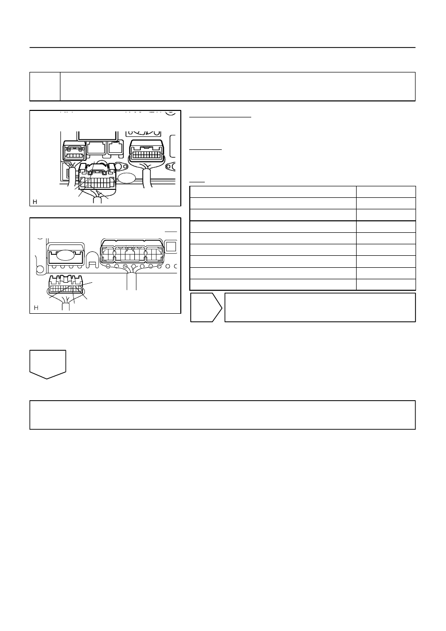
Radio and Navigation Assy
Wire Harness View:
I28752
S10
Stereo Component Amplifier Assy
Wire Harness View:
L+
R–
L–
R+
–
DIAGNOSTICS
NAVIGATION SYSTEM
DI–2275
2469
INSPECTION PROCEDURE
1
Check harness and connector (Radio and navigation assy – stereo component
amplifier assy).
PREPARATION:
Disconnect the radio and navigation assy and stereo compo-
nent amplifier assy connectors.
CHECK:
Measure the resistance according to the values in the table be-
low.
OK:
Symbol (Tester connection)
Specified condition
L+ (R30–9) – L+ (S10–3)
Below 1
Ω
L– (R30–19) – L– (S10–2)
Below 1
Ω
R+ (R30–8) – R+ (S10–5)
Below 1
Ω
R– (R30–18) – R– (S10–4)
Below 1
Ω
L+ (R30–9) – Body ground
10 k
Ω
or higher
L– (R30–19) – Body ground
10 k
Ω
or higher
R+ (R30–8) – Body ground
10 k
Ω
or higher
R– (R30–18) – Body ground
10 k
Ω
or higher
NG
Repair or replace harness or connector.
OK
Proceed to next circuit inspection shown in problem symptoms table (See page
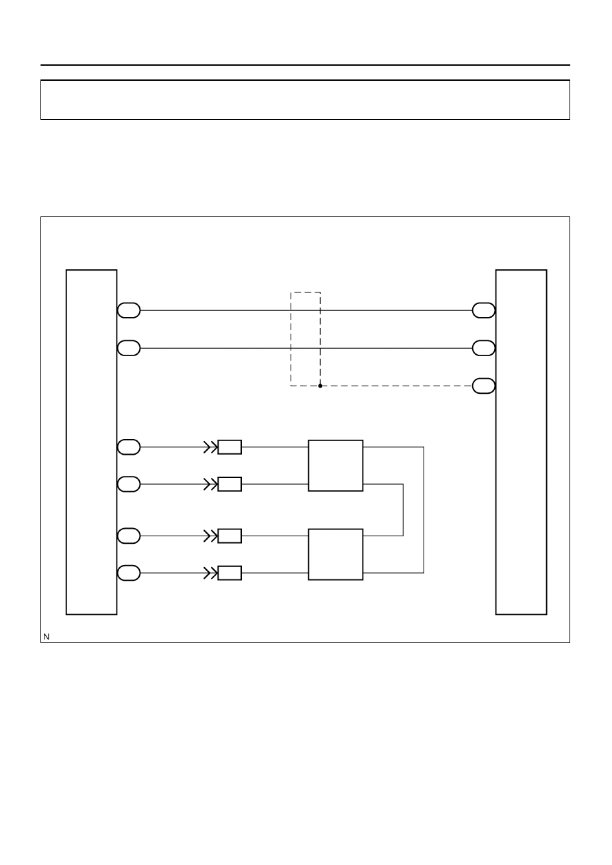
I28478
Stereo Component
Amplifier Assy
IB1
S9
T12
Tweeter LH
F14
Front Door Speaker
and Woofer LH
IB1
IB1
IB1
S9
S9
S9
WFL+
FL–
WFL–
FL+
11
2
6
17
12
2
3
4
2
3
4
1
5
4
6
7
1
R
G
L–W
L
V
P
L–W
S10
23
22
S10
INT+
INT–
G
V
P
11
13
R27
W
B
(Shielded)
Radio and Navigation Assy
IVO+
IVO–
SLD1
R27
R27
DI–2276
–
DIAGNOSTICS
NAVIGATION SYSTEM
2470
Speaker circuit (Navigation voice)
CIRCUIT DESCRIPTION
This circuit is used when the voice guidance in the radio and navigation assy is on.
Voice guidance of the navigation system is heard from the front door speaker LH via the tweeter LH.
WIRING DIAGRAM
DIDDL–01
I28759
Connector Front View:
F14
–
DIAGNOSTICS
NAVIGATION SYSTEM
DI–2277
2471
INSPECTION PROCEDURE
1
Inspect apparatus.
CHECK:
Choose the apparatus to be inspected.
RESULT:
Apparatus
Go to step
Front door speaker LH
A
Front door speaker LH and tweeter LH
B
B
Go to step 5.
A
2
Inspect front door speaker assy.
PREPARATION:
Disconnect the speaker connector.
CHECK:
Measure the resistance between the terminals of the speaker.
NOTICE:
The speaker should not be removed for checking.
OK:
Tester connection
Specified condition
1 – 2
Approx. 3.15
Ω
3 – 4
Approx. 2.78
Ω
NG
Replace front door speaker.
OK
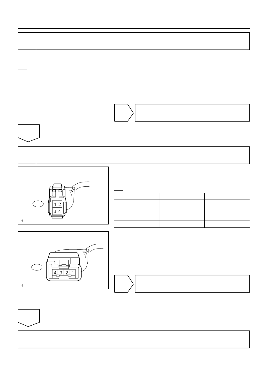
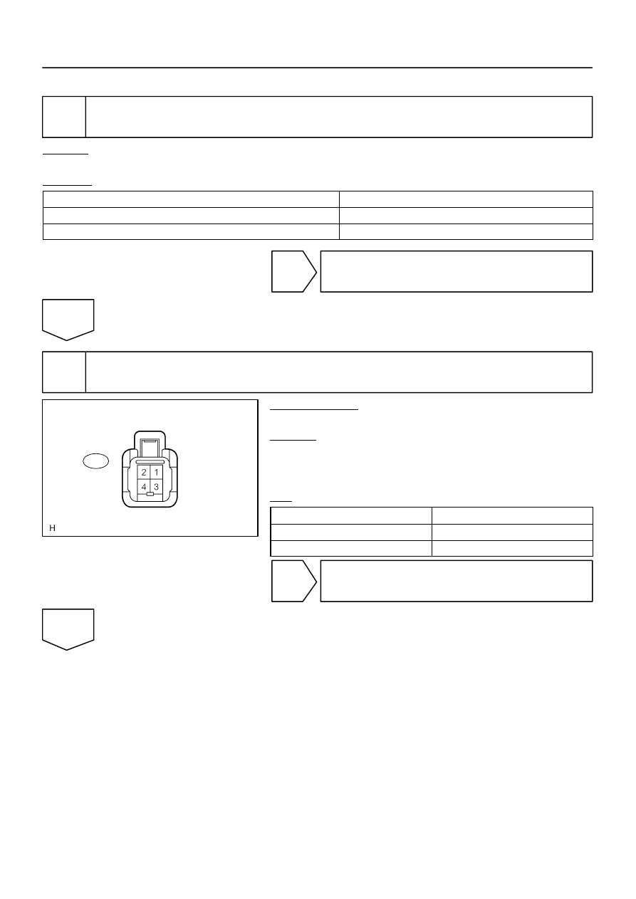
I28757
F14
Front Door Speaker
Connector Front View:
I28758
T12
Tweeter Connector front View:
DI–2278
–
DIAGNOSTICS
NAVIGATION SYSTEM
2472
3
Inspect tweeter.
CHECK:
Check that the malfunction disappears when another tweeter in good condition is installed.
OK:
Malfunction disappears.
HINT:
Connect all the connectors to the speakers.
When there is a possibility that either right or left front speaker is defective, inspect by interchanging
the right one with the left one.
OK
Replace tweeter.
NG
4
Check harness and connector (Front door speaker – tweeter).
CHECK:
Measure the resistance according to the value(s) in the table
below.
OK:
Tester connection
Condition
Specified condition
F14–1 – T12–3
Always
Below 1
Ω
F14–2 – T12–4
Always
Below 1
Ω
F14–1 – Body ground
Always
10 k
Ω
or higher
F14–2 – Body ground
Always
10 k
Ω
or higher
NG
Repair or replace harness or connector.
NG
Proceed to next circuit inspection shown on problem symptoms table (See page
).
Нет комментариевНе стесняйтесь поделиться с нами вашим ценным мнением.
Текст