Toyota Sequoia (2005). Manual — part 538
I28471
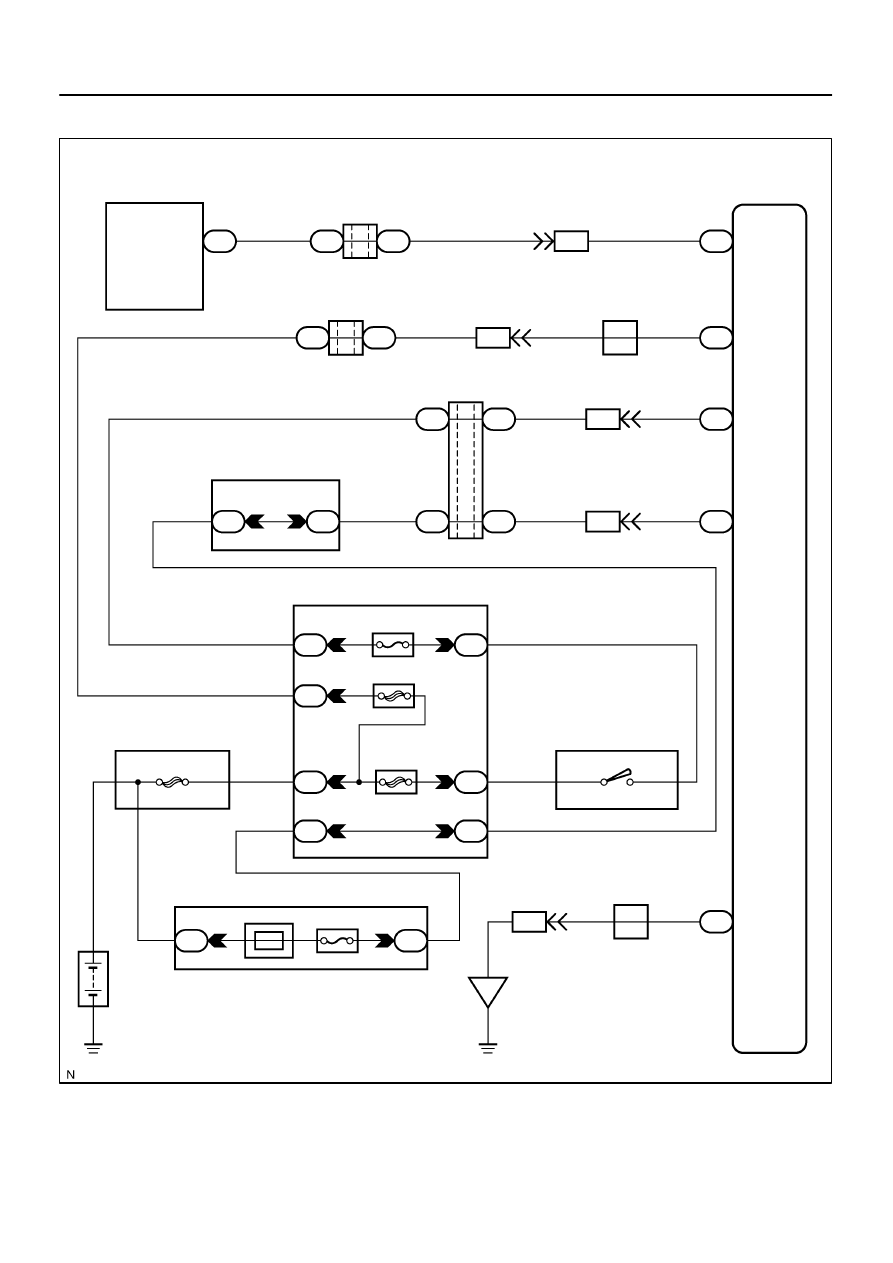
Combination Meter
Memory Seat ECU
& SW
Sub J/B No. 3
J/C
J24
J/C
Instrument Panel J/B
F10
Fusible Link Block
I18
Ignition SW
Engine Room J/B
Battery
BH
J24
J/C
J/C
J/C
C5
J33
BI2
M6
J34
J31
J32
3A
3A
J33
J34
J33
J34
BI2
BI2
BI2
M6
M6
M7
AM1
ECU–IG
1F
1L
1J
1E
1G
1C
1
4
6
1
16
2
1C
2
4
PWR SEAT
1
2
M7
BI2
ECU–B
Short Pin
2D
2C
1
8
ALT
IG1
AM1
1
2
B
B
W–B
W–B
W–B
B
5
8
W
W–L
W–R
W–R
B–Y
B–R
L–O
3
W–R
W–R
W–R
W–R
B–R
B–R
B–R
L–O
L–O
L–O
L–O
3
1
11
8
15
16
4
1
5
A
9
C
A
G
G
A
W
W
W
17
30
C
L
I
F
MPX1
+B
IG
SYSB
GND
1
4
–
DIAGNOSTICS
MULTIPLEX COMMUNICATION SYSTEM
DI–1947
2141
WIRING DIAGRAM
DI–1948
–
DIAGNOSTICS
MULTIPLEX COMMUNICATION SYSTEM
2142
INSPECTION PROCEDURE
1
Check power seat control system (w/ driving position memory).
CHECK:
Check the operation of the power seat.
OK:
The power seat control system operates normally.
NG
Go to power source circuit (See page
OK
2
Check wire harness (Memory seat ECU & switch – combination meter).
PREPARATION:
Disconnect connector ”M6” of the memory seat ECU and ”C5” of the combination meter.
CHECK:
Measure the resistance according to the values in the table below.
OK:
Tester connection (Symbols)
Condition
Specified condition
M6–1 (MPX1) – C5–30
Always
Below 1
Ω
M6–1 (MPX1) – Body ground
Always
10 k
Ω
or higher
NG
Repair or replace wire harness or connector.
OK
Replace memory seat ECU & switch.
If the problem recurs even after replacement, replace the body ECU.
–
DIAGNOSTICS
MULTIPLEX COMMUNICATION SYSTEM
DI–1949
2143
DTC
B1273
Sliding roof ECU communication stop
(w/ Sliding roof)
CIRCUIT DESCRIPTION
This DTC is indicated when communication fails between the sliding roof ECU and body ECU.
DTC No.
DTC Detecting Condition
Trouble Area
B1273
No communication from sliding roof ECU for more than 10
Sliding roof ECU
Wi
h
B1273
No communication from sliding roof ECU for more than 10
seconds.
Wire harness
Body ECU
DIDFL–01
I28472
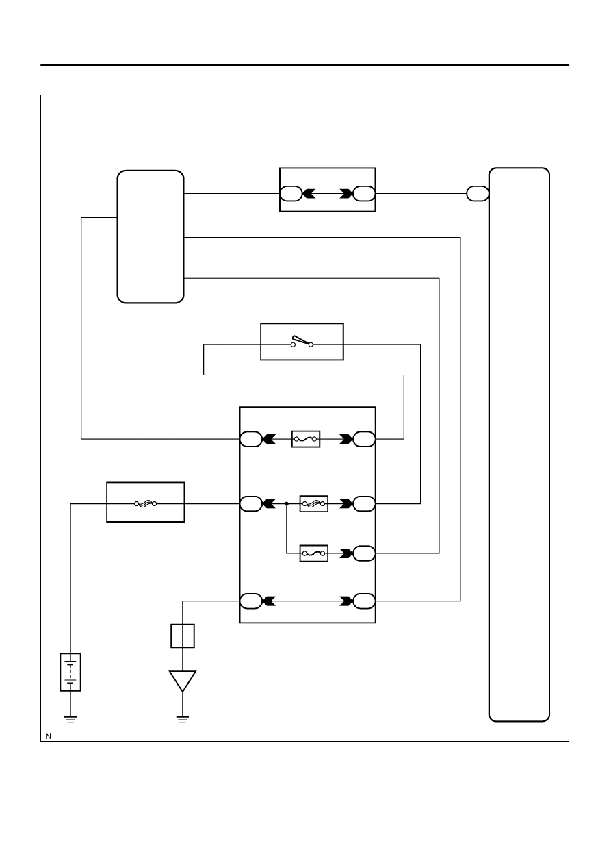
S19
Sliding Roof
Control ECU
Instrument Panel J/B
Body ECU
I18
Ignition SW
Instrument Panel J/B
F10
Fusible Link Block
Battery
IE
J8
J/C
MPX1
E
B
IG
MPX3
IG1
AM1 1
2
AM1
ECU–IG
1F
1L
1M
B7
1
6
1
2
1C
4
SUN–ROOF
7
ALT
5
8
W
A
W–B
B
W–B
1
5
1M
1M
10
W–L
L–W
B–R
W–L
B–Y
2
7
5
1M
1G
L–W
W–B
G–O
G–O
B–R 8
9
12
20
1C
DI–1950
–
DIAGNOSTICS
MULTIPLEX COMMUNICATION SYSTEM
2144
WIRING DIAGRAM
Нет комментариевНе стесняйтесь поделиться с нами вашим ценным мнением.
Текст