Toyota Sequoia (2005). Manual — part 539
–
DIAGNOSTICS
MULTIPLEX COMMUNICATION SYSTEM
DI–1951
2145
INSPECTION PROCEDURE
1
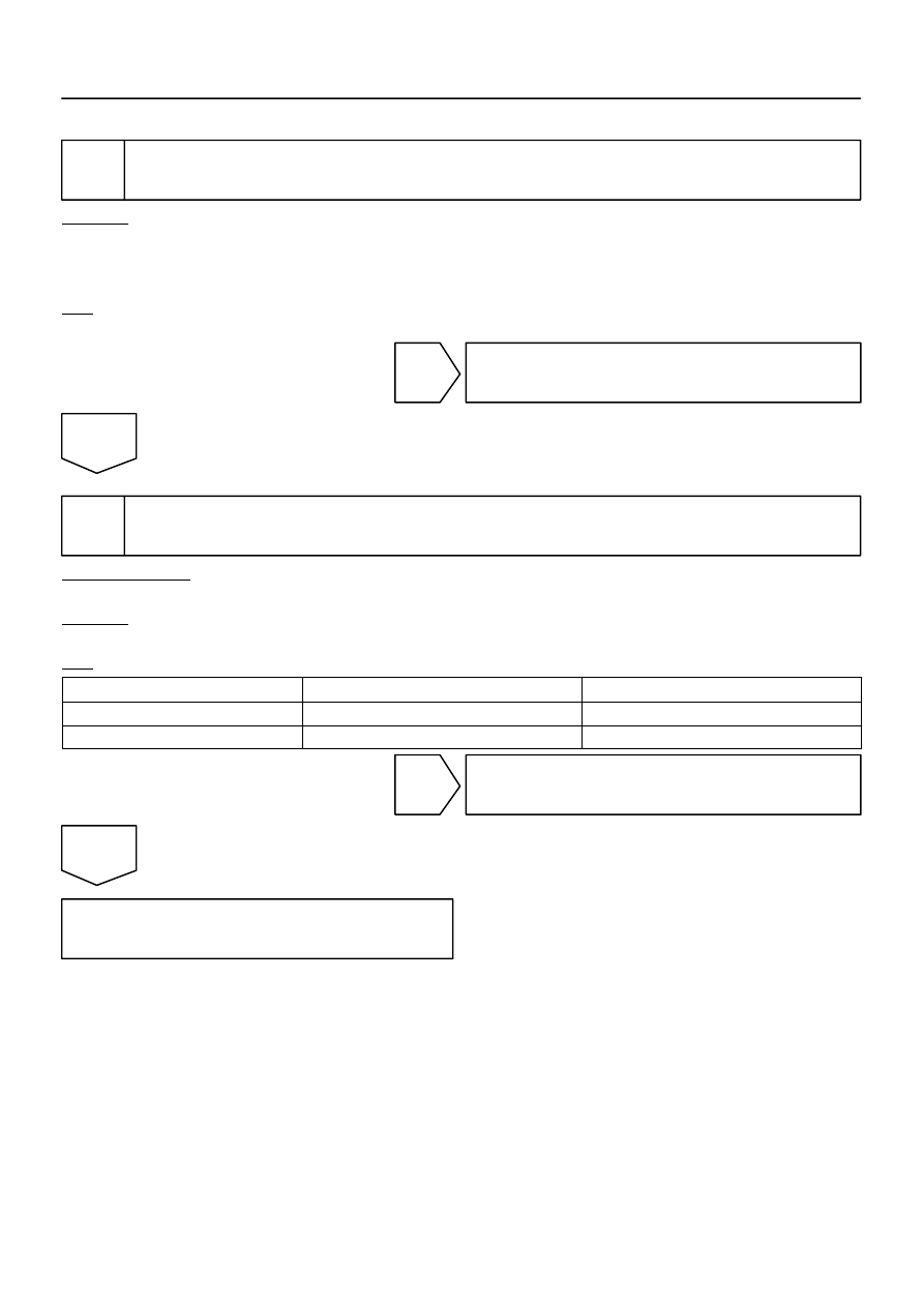
Check sliding roof ECU.
CHECK:
Check that the operation of the sliding roof function is normal.
HINT:
The operating condition of the sliding roof ECU CPU can be diagnosed with this check.
OK:
The sliding roof operates normally.
NG
Go to power source circuit (See page
OK
2
Check wire harness and connector (Sliding roof control ECU – body ECU).
PREPARATION:
Disconnect connector ”B7” of the body ECU and connector ”S19” of the sliding roof ECU.
CHECK:
Measure the resistance according to the values in the table below.
OK:
Tester connection (Symbols)
Condition
Specified condition
S19–2 (MPX1) – B7–20 (MPX3)
Always
Below 1
Ω
S19–2 (MPX1) – Body ground
Always
10 k
Ω
or higher
NG
Repair or replace wire harness.
OK
Replace the sliding roof ECU.
If the problem recurs even after replacement, replace the body ECU.
DI–1952
–
DIAGNOSTICS
MULTIPLEX COMMUNICATION SYSTEM
2146
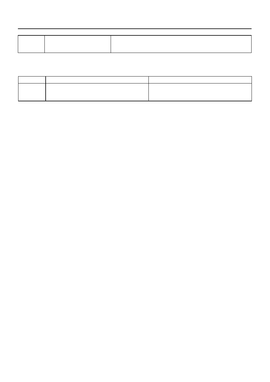
DTC
B1287
Back door ECU communication stop
CIRCUIT DESCRIPTION
This DTC is indicated when communication fails between the back door ECU and body ECU.
DTC No.
DTC Detecting Condition
Trouble Area
B1287
No communication from back door ECU for more than 10 se-
conds.
Back door ECU
Wire harness
Body ECU
DIDFM–01
I28473
Combination Meter
F18
Front Passenger
Door ECU
Back Door ECU
Sub J/B No. 3
I18
Ignition SW
Instrument Panel J/B
F10
Fusible Link Block
Engine Room J/B
Instrument Panel J/B
Sub J/B No. 3
Battery
BJ
J19
J/C
J22
J/C
J37
J/C
J/C
J/C
J33
J34
J33
J34
C5
B11
BF1
BD2
II2
B11
B11
B11
BF1
BD2
BD2
BF1
IN1
AM1
ECU–IG
1F
1L
1G
1C
1
4
6
1
2
1C
15
4
1
2
PWR No. 5
ALT
5
8
4
3C
3A
8
8
A
A
G
A
B
H
IG1
AM1
1
2
6
7
31
2
1
6
4
2
5
11
11
14
8
B
B
B
B
B
20 (*1)
LG–R
B–R
LG–R
LG–R
LG–R
B–R
B–R
B–R
B–R
B–R
B–Y
W–L
W
B
B
L–W
L–W
L–W
L–W
W–R
W–R
W–R
W–R
W–R
W–R
W–B
W–B
W–B
W–B
A
2
12
B
B
3
5
B11
B11
10
12
1
1
2
3A
3C
BD2
BF1
BF1
BD1
IN1
BF1
BD1
IC4
2
3
8
1
1J
1E
2C
2D
ECU–B
Short Pin
2
3
10
MPX1
SIG
BDR
GND
MPX2
BECU
MPX1
*1: w/ Driving Position Memory
*2: w/o Driving Position Memory
10 (*2)
–
DIAGNOSTICS
MULTIPLEX COMMUNICATION SYSTEM
DI–1953
2147
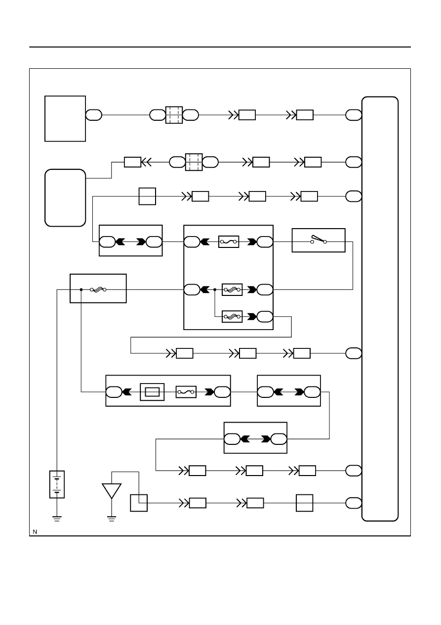
WIRING DIAGRAM
DI–1954
–
DIAGNOSTICS
MULTIPLEX COMMUNICATION SYSTEM
2148
INSPECTION PROCEDURE
1
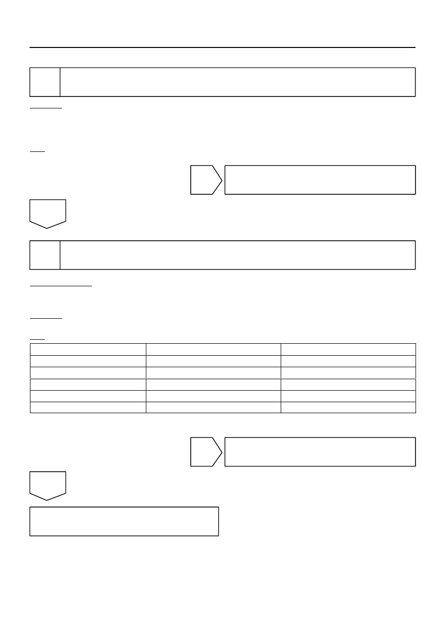
Check back door ECU.
CHECK:
Check that the operation of the rear wiper motor function is normal.
HINT:
With this inspection, the back door ECU CPU can be diagnosed if it works normally or not.
OK:
Rear wiper motor operates normally.
NG
Replace the back door ECU.
OK
2
Check wire harness and connector (Back door ECU – combination meter, back
door ECU – passenger door ECU).
PREPARATION:
Disconnect connector ”F18” of the passenger door ECU, connector ”B11” of the back door ECU and connec-
tor ”C5” of the combination meter ECU.
CHECK:
Measure the resistance according to the values in the table below.
OK:
Tester connection (Symbols)
Condition
Specified condition
B11–2 (MPX1) – C5–31
Always
Below 1
Ω
B11–1 (MPX2) – F18–10 (*1)
Always
Below 1
Ω
B11–1 (MPX2) – F18–20 (*2)
Always
Below 1
Ω
B11–1 (MPX2) – Body ground
Always
10 k
Ω
or higher
B11–2 (MPX1) – Body ground
Always
10 k
Ω
or higher
*1: w/ Driving Position Memory
*2: w/o Driving Position Memory
NG
Repair or replace wire harness.
OK
Replace the back door ECU.
If the problem recurs even after replacement, replace the body ECU.
Нет комментариевНе стесняйтесь поделиться с нами вашим ценным мнением.
Текст