Toyota Sequoia (2005). Manual — part 536
–
DIAGNOSTICS
MULTIPLEX COMMUNICATION SYSTEM
DI–1939
2133
2
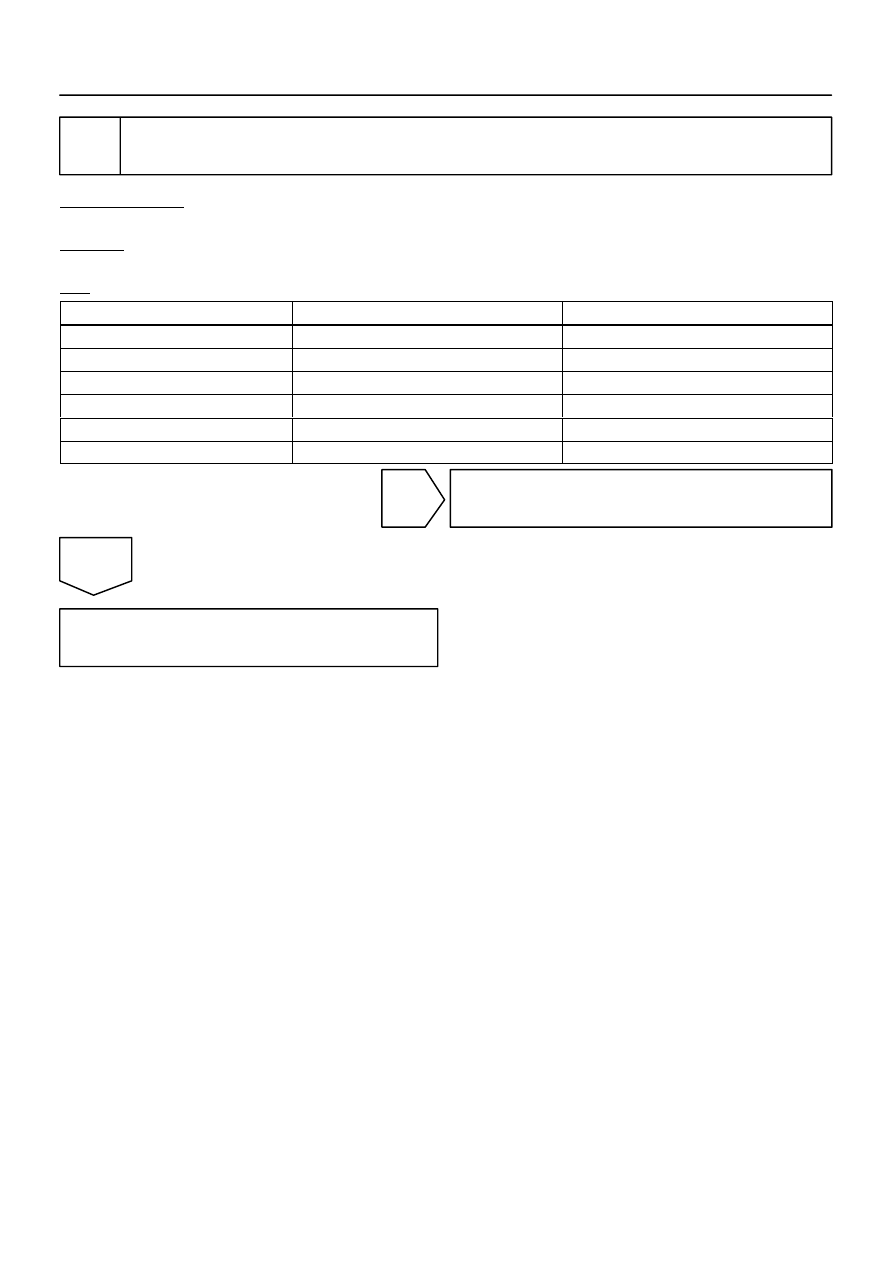
Check wire harness and connector between automatic light control sensor and
body ECU.
PREPARATION:
Disconnect connector ”A27” of the automatic light control sensor and connector ”B6” of the body ECU.
CHECK:
Measure the resistance according to the values in the table below.
OK:
Tester connection (Symbols)
Condition
Specified condition
A27–4 – B6–12 (CLTS)
Always
Below 1
Ω
A27–1 – B6–4 (CLTB)
Always
Below 1
Ω
A27–3 – B6–3 (CLTE)
Always
Below 1
Ω
A27–4 – Body ground
Always
10 k
Ω
or higher
A27–1 – Body ground
Always
10 k
Ω
or higher
A27–3 – Body ground
Always
10 k
Ω
or higher
NG
Repair or replace wire harness or connector.
OK
Replace the body ECU.

DI–1940
–
DIAGNOSTICS
MULTIPLEX COMMUNICATION SYSTEM
2134
DTC
B1262
A/C ECU communication stop
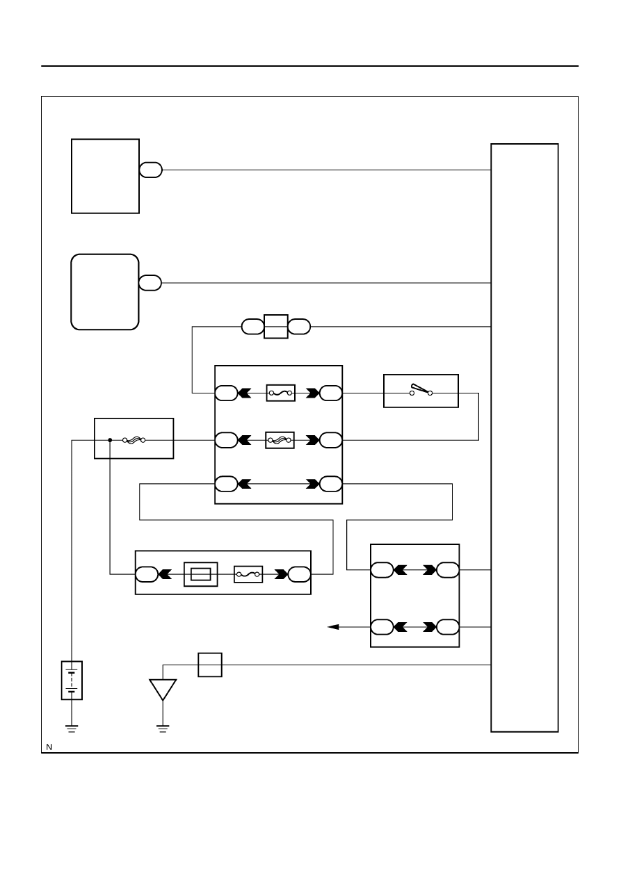
CIRCUIT DESCRIPTION
This DTC is indicated when communication fails between the integration control and panel and the body
ECU.
DTC No.
DTC Detecting Condition
Trouble Area
B1262
No communication from integration control and panel for more
than 10 seconds.
A/C ECU (Integration control and panel)
Wire harness
Body ECU
DIDFI–01
I28469
I19
Integration Control
and Panel
Body ECU
I18
Ignition SW
Combination Meter
F10
FL Block
To Ignition
Switch
J43
J/C
IG
Battery
DOME
ALT
AM1
CIG
ACC
AM1
Short Pin
J/C
MPX–
ACC
+B
MPX+
MPX2
IG+
GND
C5
B5
J15
1E
1L
1J
J15
1E
1C
1C
2D
2C
3A
3E
3A
3E
O
B
R
W
W–L
O
B
R
P
P
P
R
R–L
R–L
L–Y
LG–B
D
D
32
24
13
3
11
3
1
1
1
8
6
20
1
5
2
8
5
4
1
3
6
6
16
15
1
2
10
Instrument Panel J/B
Engine Room J/B
Sub J/B No.3
A
A
–
DIAGNOSTICS
MULTIPLEX COMMUNICATION SYSTEM
DI–1941
2135
WIRING DIAGRAM
DI–1942
–
DIAGNOSTICS
MULTIPLEX COMMUNICATION SYSTEM
2136
INSPECTION PROCEDURE
1
Check air conditioning system.
CHECK:
Check the operation of the air conditioning system.
OK:
The air conditioning system operates normally.
NG
Go to air conditioning system
OK
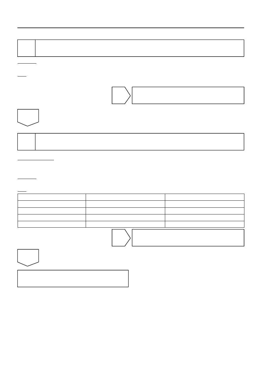
2
Check wire harness (Integration control and panel – combination meter, integra-
tion control and panel – body ECU).
PREPARATION:
Disconnect connector ”B5” of the body ECU connector, ”I19” of the integration control and panel and connec-
tor ”C5” of the combination meter.
CHECK:
Measure the resistance according to the values in the table below.
OK:
Tester connection (Symbols)
Condition
Specified condition
C5–32 – I19–13 (MPX–)
Always
Below 1
Ω
B5–24 (MPX2) – I19–3 (MPX+)
Always
Below 1
Ω
C5–32 – Body ground
Always
10 k
Ω
or higher
B5–24 (MPX2) – Body ground
Always
10 k
Ω
or higher
NG
Repair or replace wire harness.
OK
Replace integration control and panel.
If the problem recurs even after replacement, replace the body ECU.
Нет комментариевНе стесняйтесь поделиться с нами вашим ценным мнением.
Текст