Toyota Sequoia (2005). Manual — part 545
–
DIAGNOSTICS
AUDIO SYSTEM
DI–1975
2169
(d)
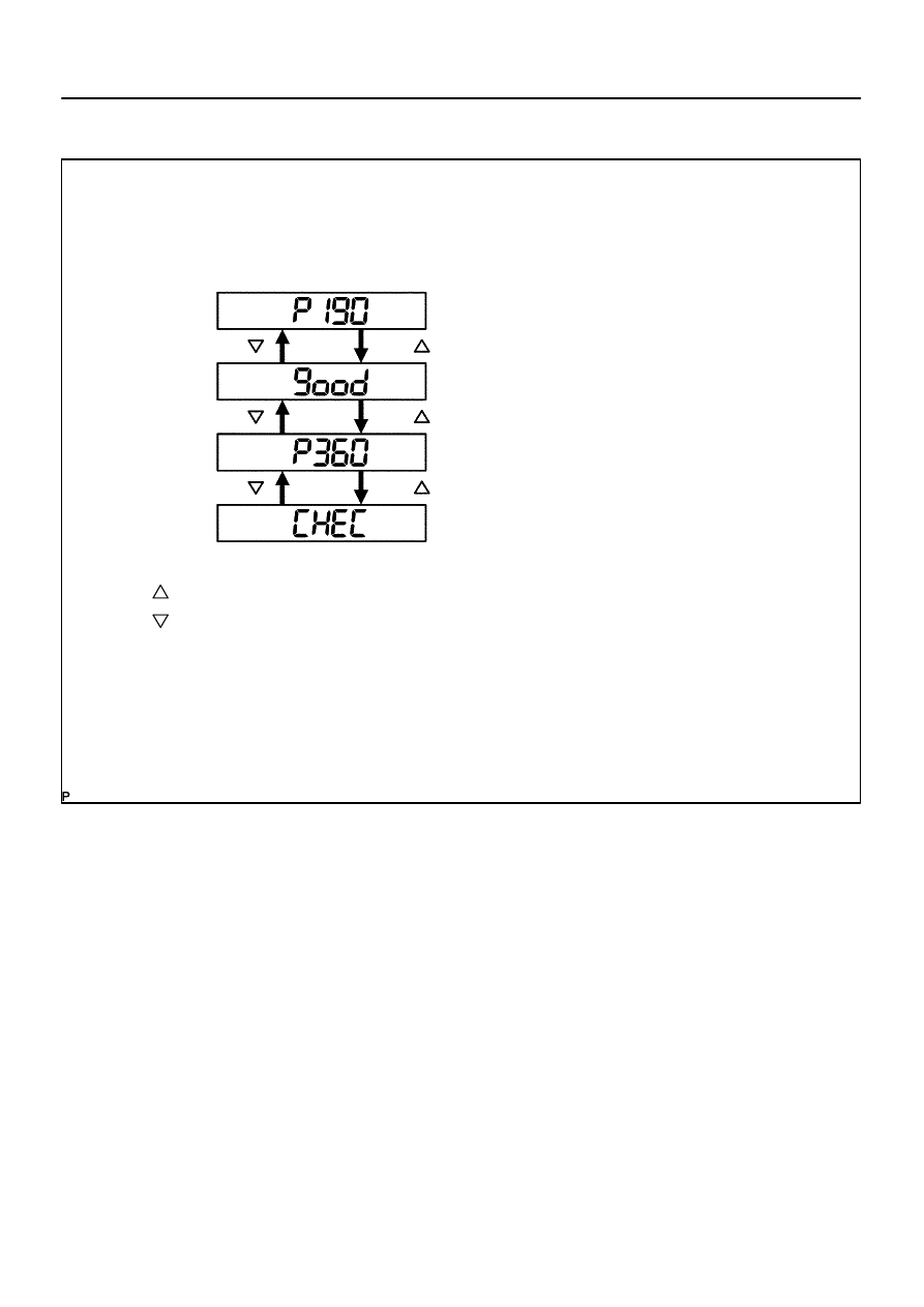
Service Check Mode Result Display (for checking the current and the past system conditions).
(1)
Press the ”SEEK TRACK” switch to see the check result of each component.
I28309
The illustration shows the case that the system has 2 devices with codes 190 and 360, and the device (code
360) has a trouble.
The check result is displayed in ascending order of device code. The device code is displayed first, and then
the check result.
P–––indicates physical address
190–––physical address
good–––”The component is normal”.
P–––indicates physical address
360–––physical address
CHEC–––”Check needed”.
: TUNE/TRACK UP
: TUNE/TRACK DOWN
DI–1976
–
DIAGNOSTICS
AUDIO SYSTEM
2170
(2)
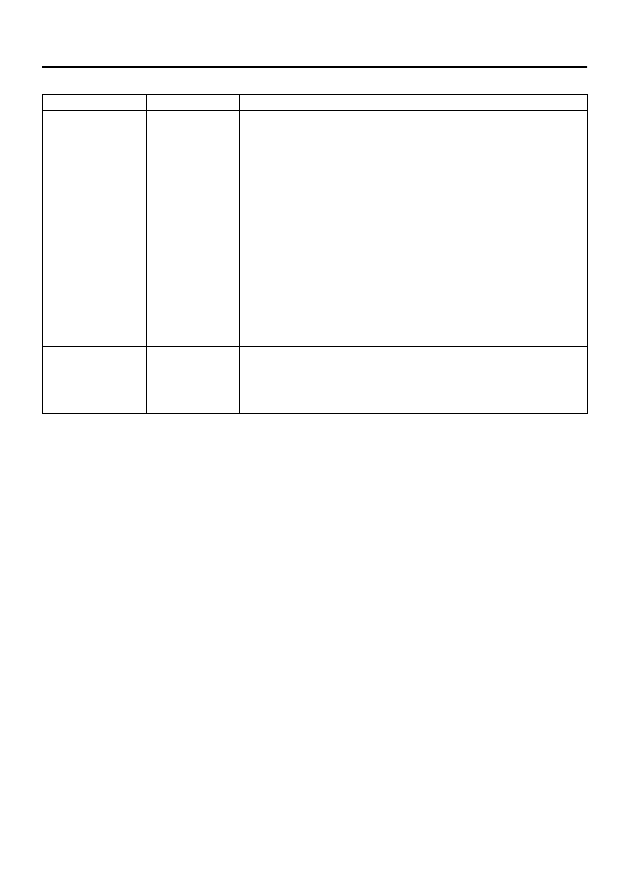
Check Result Display.
Display
Original Language
Meaning
Action to be taken
good
Good (normal)
No DTCs are detected in both ”System Check Mode” and
”Diagnostic Memory Mode”.
–
NCON
No connection
The system recognized the component when it was regis-
tered, but the component gives no response to the ”Diagnos-
tic Mode ON Request”.
Check the power source cir-
cuit and the communication
circuit of the component indi-
cated by the component
code (physical address).
ECHN
Exchange
One or more DTCs for ”Exchange” are detected in either
”System Check Mode” or ”Diagnostic Memory Mode”.
Go to the detailed informa-
tion mode to check the
trouble area referring to the
DTC list.
CHEC
Check
When no DTCs are detected for ”Exchange”, one or more
DTCs for ”Check” are detected in either ”System Check
Mode” or ”Diagnostic Memory Mode”.
Go to the detailed informa-
tion mode to check the
trouble area referring to the
DTC list.
OLD
Old version
Old DTC application is identified and DTC is detected in ei-
ther ”System Check Mode” or ”Diagnostic Memory Mode”.
–
NRES
No response
The device gives no response to any one of ”System Check
Mode ON Request”, ”System Check Result Request” and
”Diagnostic Memory Request”.
Check the power source cir-
cuit and the communication
circuit of the component indi-
cated by the component
code (physical address).
(3)
To perform the Service Check again, press the preset switch ”1”.
(e)
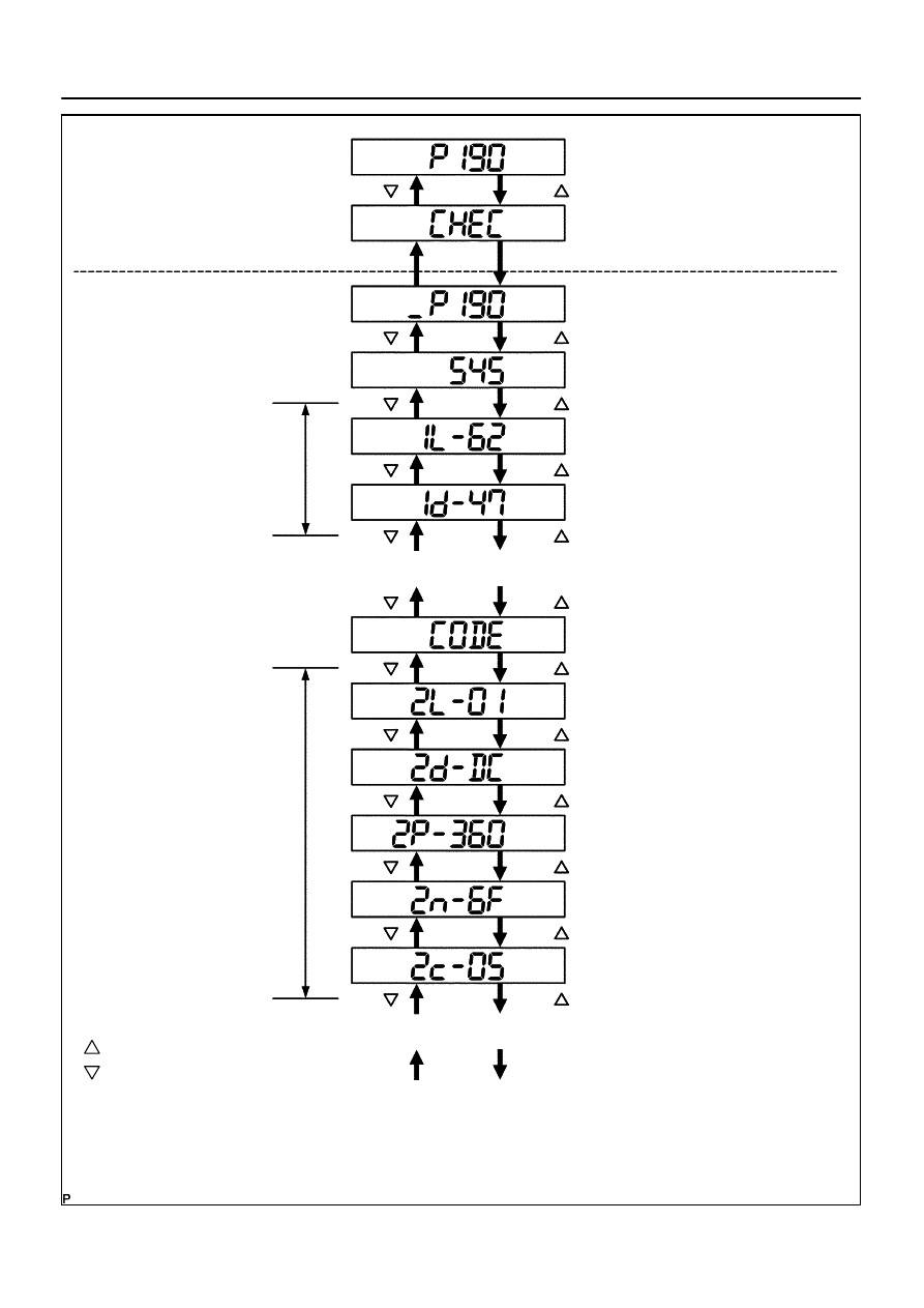
Detailed Information Mode (when displaying the DTC for a trouble component)
(1)
With ”CHEC” or ”ECHN” being displayed, press the preset switch ”2” to go to the detailed informa-
tion mode.
(2)
Press the ”SEEK TRACK” switch to display the ”System Check Result (SYS)” and ”Diagnostic
Memory Response (CODE)”.
I28310
Service Check Mode
Detailed Information Mode
DISC/CH/PROG DOWN
Detailed information
of the first code
is displayed
Detailed information
of the second code
is displayed
Continue to display detailed information
when more than one DTC is detected.
The illustration shows the case that the component with code 190 has DTC ”47” and ”dC” as a result of the
system check and the diagnosis memory response.
The detailed information mode shows the system check result first, then the diagnosis memory response result.
(*1): As for DTC that does not have any sub code, sub code is not displayed.
P–––indicates physical address
190–––physical address
SYS–––system check result
P–––indicates physical address
360–––sub code
6F–––connection
check number
1–––the first code
62–––logical address
DC–––DTC
CODE–––diagnosis memory
response result
2–––the second code
01–––logical address
05–––the number of times of
occurrence
(in decimal)
47–––DTC
Continue to display detailed information
when more than one DTC is detected.
*
From *
To *
(*1)
: TUNE/TRACK UP
: TUNE/TRACK DOWN
DISC/CH/PROG UP
–
DIAGNOSTICS
AUDIO SYSTEM
DI–1977
2171

DI–1978
–
DIAGNOSTICS
AUDIO SYSTEM
2172
(3)
Displayed Items in Detailed Information Mode
Division Code for
DTC display
Meaning
The order of detailed information displayed when the ”TUNE
UP” switch is pressed. (The order is reversed when the
”TUNE DOWN” switch is pressed.)
SYS
System check result is displayed.
Logical address
→
DTC
CODE
Diagnostic memory check result is displayed.
Logical address
→
DTC
→
Sub code
→
Connection confirmation number
→
The number of times of occurrence
(4)
Check the trouble area referring to the DTC list.
(5)
To return to the service check mode, press the preset switch ”3”.
2.
DTC CLEAR
(a)
Clearing Individual DTC Memory (when clearing the memory of the DTC detected in the past individual-
ly)
Press the preset switch ”5” for 2 seconds or more while the ”ECHN” is displayed in the service check
mode or during the detailed information mode.
HINT:
Beep sound is emitted once when the DTC memory is completely cleared.
When the DTC memory is cleared, only the component code (physical address) is displayed for the
target component.
To check DTCs, press the preset switch ”1” and perform the service check again.
(b)
Clearance of all the DTC memory (when clearing all the memory of the DTCs detected in the past)
(1)
Start the diagnostic mode after repairing the trouble area.
(2)
Press the preset switch ”5” for 2 seconds or more (”CLR” is displayed at this time).
HINT:
Beep sound is emitted once when the DTC memory is completely cleared.
When the DTC memory for all the component is cleared, only the component codes (physical address)
are displayed.
(3)
Press the preset switch ”1” to perform the service check again, and check that no DTCs are dis-
played for all the component codes (physical address).
(c)
Finishing Diagnostic Mode.
Press the ”DISC” for 2 seconds or more, or turn the ignition switch off.
Нет комментариевНе стесняйтесь поделиться с нами вашим ценным мнением.
Текст