Toyota Sequoia (2005). Manual — part 862
BE050–15
I28403
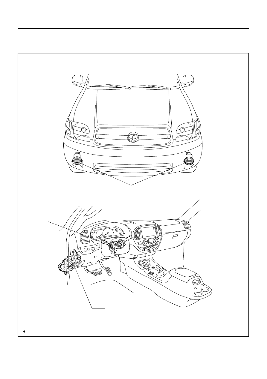
Front Fog Light
Combination Switch
Front Fog Light Switch
Instrument Panel J/B
Fog Light Relay
Fog Fuse
–
BODY ELECTRICAL
FOG LIGHT SYSTEM
BE–33
3437
FOG LIGHT SYSTEM
LOCATION
BE0HZ–08
I12795
OFF
ON
5 4
1
2
3
15
16
6
7
8
9
10
11
17
141312
I05027
1
2
3
5
5
2
1
3
BE–34
–
BODY ELECTRICAL
FOG LIGHT SYSTEM
3438
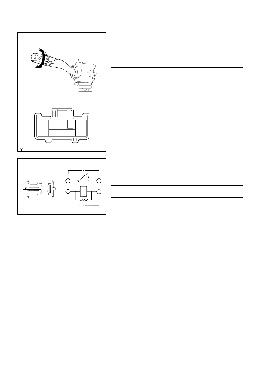
INSPECTION
1.
INSPECT FOG LIGHT SWITCH CONTINUITY
Switch position
Tester connection
Specified condition
OFF
–
No continuity
ON
10 – 11
Continuity
If continuity is not as specified, replace the switch.
2.
INSPECT FOG LIGHT RELAY CONTINUITY
Condition
Tester connection
Specified condition
Constant
1 – 2
Continuity
Constant
3 – 5
No continuity
Apply B+ between
terminals 1 and 2.
3 – 5
Continuity
If continuity is not as specified, replace the relay.
BE033–09
I28404
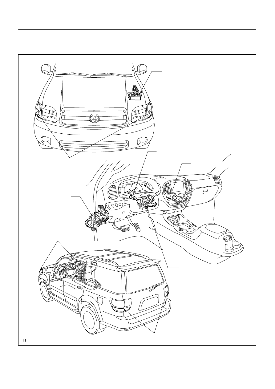
Turn Signal Light
Hazard Warning Switch
Combination Switch
Turn Signal Switch
Ignition Switch
Instrument Panel J/B
FLASHER Relay
Turn Signal Light
Turn Signal Light
Engine Room J/B
TURN HAZ Fuse
–
BODY ELECTRICAL
TURN SIGNAL AND HAZARD WARNING SYSTEM
BE–35
3439
TURN SIGNAL AND HAZARD WARNING SYSTEM
LOCATION
BE2DD–03
I12796
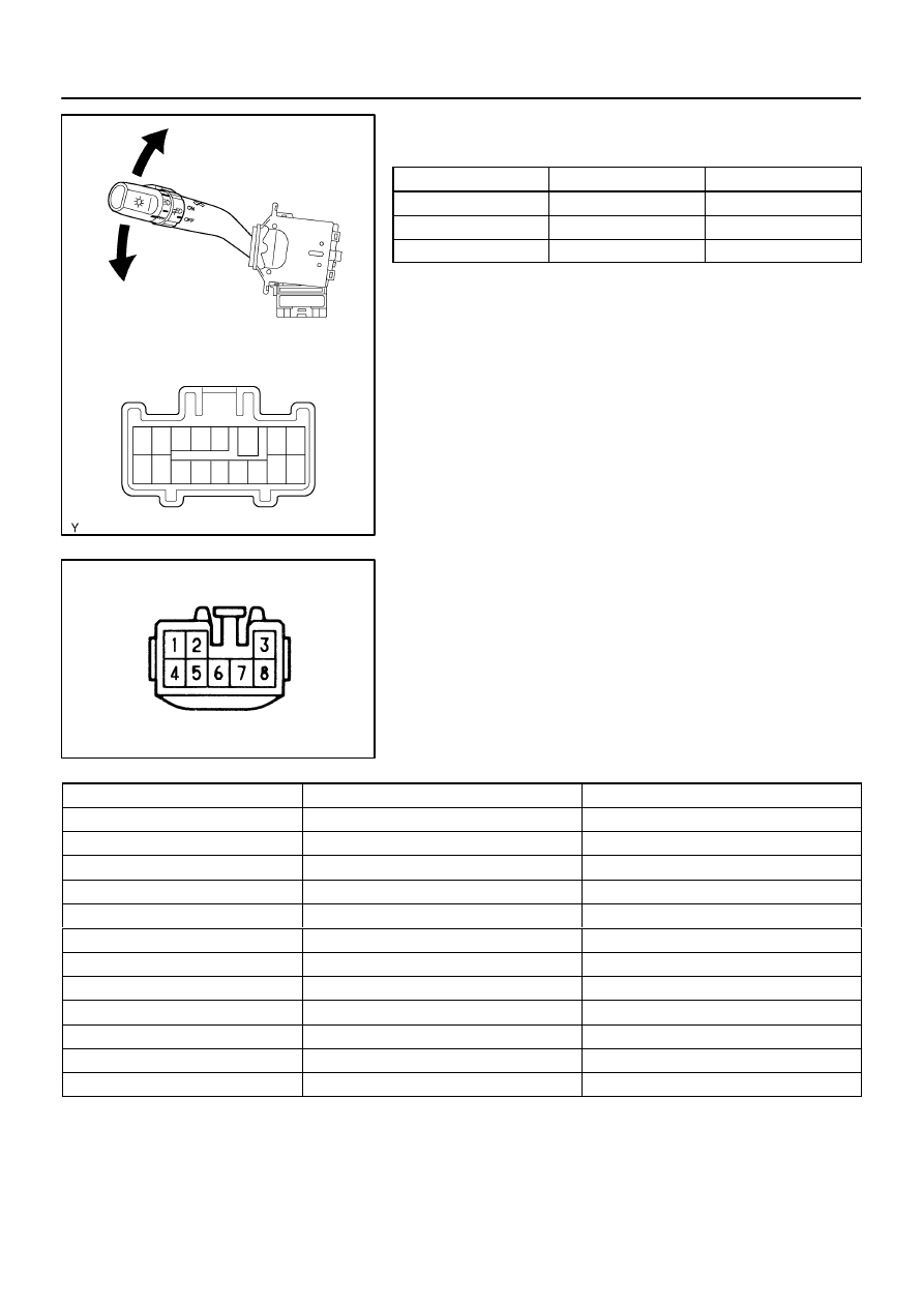
Right Turn
2
4
5
7
8
9
6
3
1
10
11
12
13
14
15
16
17
Left Turn
I04046
Wire Harness Side:
BE–36
–
BODY ELECTRICAL
TURN SIGNAL AND HAZARD WARNING SYSTEM
3440
INSPECTION
1.
INSPECT TURN SIGNAL SWITCH CONTINUITY
Switch position
Tester connection
Specified condition
Left turn
1 – 2
Continuity
Neutral
–
No continuity
Right turn
2 – 3
Continuity
If continuity is not as specified, replace the switch.
2.
Connector disconnected:
INSPECT TURN SIGNAL FLASHER CIRCUIT
Disconnect the connector from the turn signal flasher and in-
spect the connector on the wire harness side as shown in the
table below.
Tester connection
Condition
Specified condition
1 – Ground
Ignition switch LOCK or ACC
No voltage
1 – Ground
Ignition switch ON
Battery positive voltage
2 – Ground
Always
Continuity
3 – Ground
Always
Continuity
4 – Ground
Always
Battery positive voltage
5 – Ground
Turn signal switch RIGHT or OFF
No Continuity
5 – Ground
Turn signal switch LEFT
Continuity
6 – Ground
Turn signal switch LEFT or OFF
No Continuity
6 – Ground
Turn signal switch RIGHT
Continuity
7 – Ground
Always
Continuity
8 – Ground
Hazard warning switch OFF
No Continuity
8 – Ground
Hazard warning switch ON
Continuity
If the circuit is as specified, perform the inspection on the next
step.
If the circuit is not as specified, inspect the circuit connected to
other parts.
Нет комментариевНе стесняйтесь поделиться с нами вашим ценным мнением.
Текст