Toyota Sequoia (2005). Manual — part 860
BE0HV–12
I28402
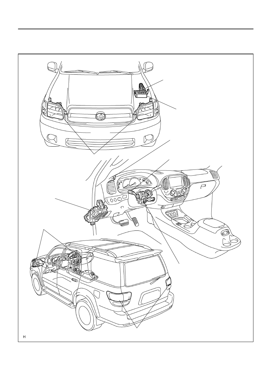
Engine Room Relay Block No. 2
DRL No. 4 Relay (*1)
DIMMER Relay (*1)
H–LP LL Fuse (*1)
H–LP RL Fuse (*1)
H–LP LH Fuse (*1)
H–LP RH Fuse (*1)
Headlight
Combination Switch
Light Control Switch
Headlight Dimmer Switch
Ignition Switch
Taillight
Instrument Panel J/B
Integration Relay
Taillight Relay
Tail Fuse
Headlight
Engine Room J/B
HEAD Relay
DRL Fuse (*1)
H–LP LH Fuse (*2)
H–LP RH Fuse (*2)
Automatic Light Control Sensor
(*1): w/ Daytime Running Light
(*2): w/o Daytime Running Light
–
BODY ELECTRICAL
HEADLIGHT AND TAILLIGHT SYSTEM
BE–25
3429
HEADLIGHT AND TAILLIGHT SYSTEM
LOCATION
BE0HW–09
F17994
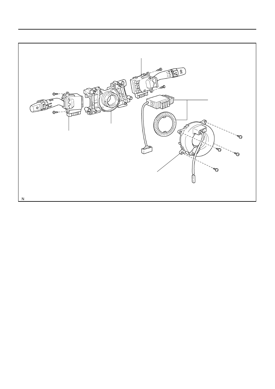
Combination Switch
Wiper and Washer Switch
Spiral Cable
Switch Body
Combination Switch
Light Control Switch
Headlight Dimmer Switch
Steering Angle
Sensor
BE–26
–
BODY ELECTRICAL
HEADLIGHT AND TAILLIGHT SYSTEM
3430
COMPONENTS
I12794
13
16 1514
9
8
17
HI
AUTO
LO
OFF
Flash
TAIL
3
2 1
5 4
6
7
10
12 11
BE2MT–01
I18635
1
2
3
4
5
I05027
1
2
3
5
1
2
3
5
I18635
1
2
3
4
5
–
BODY ELECTRICAL
HEADLIGHT AND TAILLIGHT SYSTEM
BE–27
3431
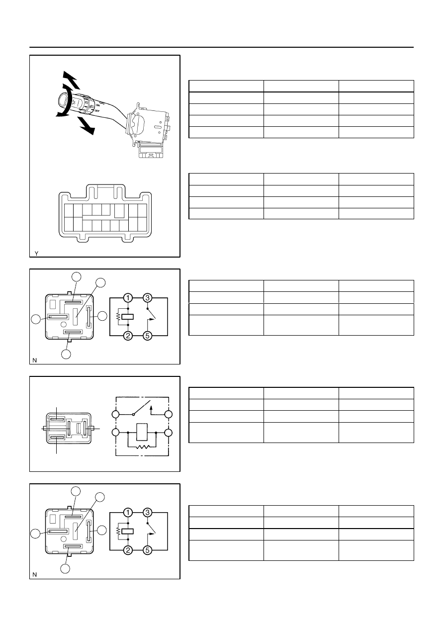
INSPECTION
1.
INSPECT LIGHT CONTROL SWITCH CONTINUITY
Switch position
Tester connection
Specified condition
OFF
–
No continuity
TAIL
14 – 16
Continuity
HEAD
13 – 14 – 16
Continuity
AUTO
12 – 16
Continuity
If continuity is not as specified, replace the switch.
2.
INSPECT HEADLIGHT DIMMER SWITCH CONTINU-
ITY
Switch position
Tester connection
Specified condition
Flash
7 – 8 – 16
Continuity
Low beam
16 – 17
Continuity
High beam
7 – 16
Continuity
If continuity is not as specified, replace the switch.
3.
INSPECT HEAD RELAY CONTINUITY
Condition
Tester connection
Specified condition
Constant
1 – 2
Continuity
Constant
3 – 5
No continuity
Apply B+ between
terminals 1 and 2.
3 – 5
Continuity
If continuity is not as specified, replace the relay.
4.
INSPECT TAILLIGHT RELAY CONTINUITY
Condition
Tester connection
Specified condition
Constant
1 – 2
Continuity
Constant
3 – 5
No continuity
Apply B+ between
terminals 1 and 2.
3 – 5
Continuity
If continuity is not as specified, replace the relay.
5.
INSPECT DRL NO. 4 RELAY CONTINUITY (w/ Daytime
Running Light)
Condition
Tester connection
Specified condition
Constant
1 – 2
Continuity
Constant
3 – 5
No continuity
Apply B+ between
terminals 1 and 2.
3 – 5
Continuity
If continuity is not as specified, replace the relay.
I18559
1
2
3
4
5
I19450
I19451
BE–28
–
BODY ELECTRICAL
HEADLIGHT AND TAILLIGHT SYSTEM
3432
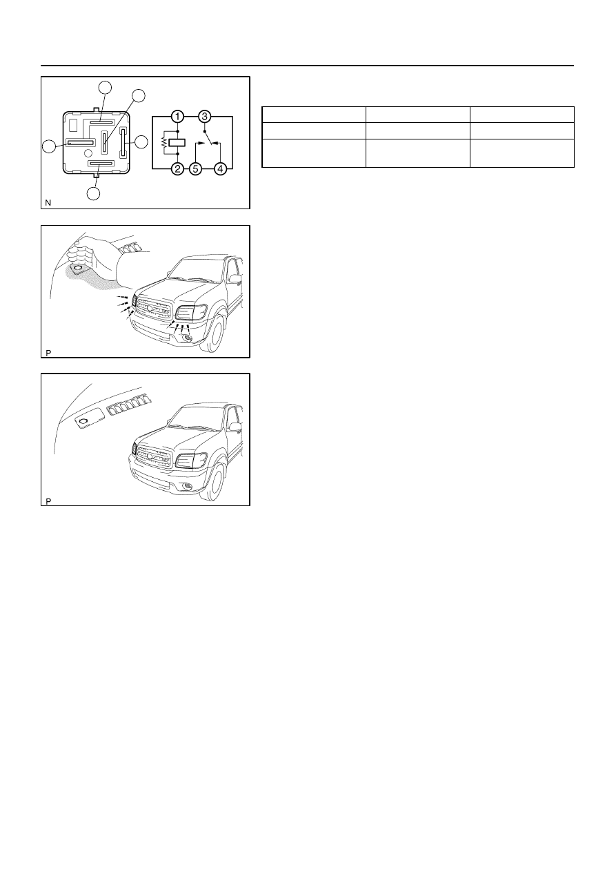
6.
INSPECT DIMMER RELAY CONTINUITY (w/ Daytime
Running Light)
Condition
Tester connection
Specified condition
Constant
1 – 2, 3 – 4
Continuity
Apply B+ between
terminals 1 and 2.
3 – 5
Continuity
If continuity is not as specified, replace the relay.
7.
AUTO ON:
INSPECT AUTOMATIC LIGHT CONTROL
(a)
Turn the ignition switch ON.
(b)
Turn the light control switch to AUTO.
(c)
Gradually cover the top of the sensor.
(d)
Check that the accessory lights and the headlights should
turn ON.
8.
AUTO OFF:
INSPECT AUTOMATIC LIGHT CONTROL
(a)
Gradually expose the sensor.
(b)
Check that the headlights and the accessory lights should
turn OFF.
9.
INSPECT LIGHTS–OFF CONDITION
(a)
Turn the ignition switch ON.
(b)
Lights auto ON:
Gradually cover the top of the sensor.
(c)
Check that the lights go off under the following conditions.
(1)
Light control switch is OFF.
(2)
The area surrounding the sensor gets bright.
(3)
After the ignition switch is turned OFF and after 30
sec. from when open doors are all closed.
10.
INSPECT LIGHTS–ON CONDITION
(a)
Open the driver’s door while the ignition switch is OFF.
(b)
Turn the light control switch to AUTO leaving the door
open and cover the top of the sensor. Make sure that the
lights go on when the ignition switch is turned ON.
11.
ADJUST AUTOMATIC LIGHT CONTROL SENSOR
(See page
Нет комментариевНе стесняйтесь поделиться с нами вашим ценным мнением.
Текст