Toyota Sequoia (2005). Manual — part 804
BR0TC–06
F13317
F13318
F13319
BR–38
–
BRAKE
REAR BRAKE CALIPER
3205
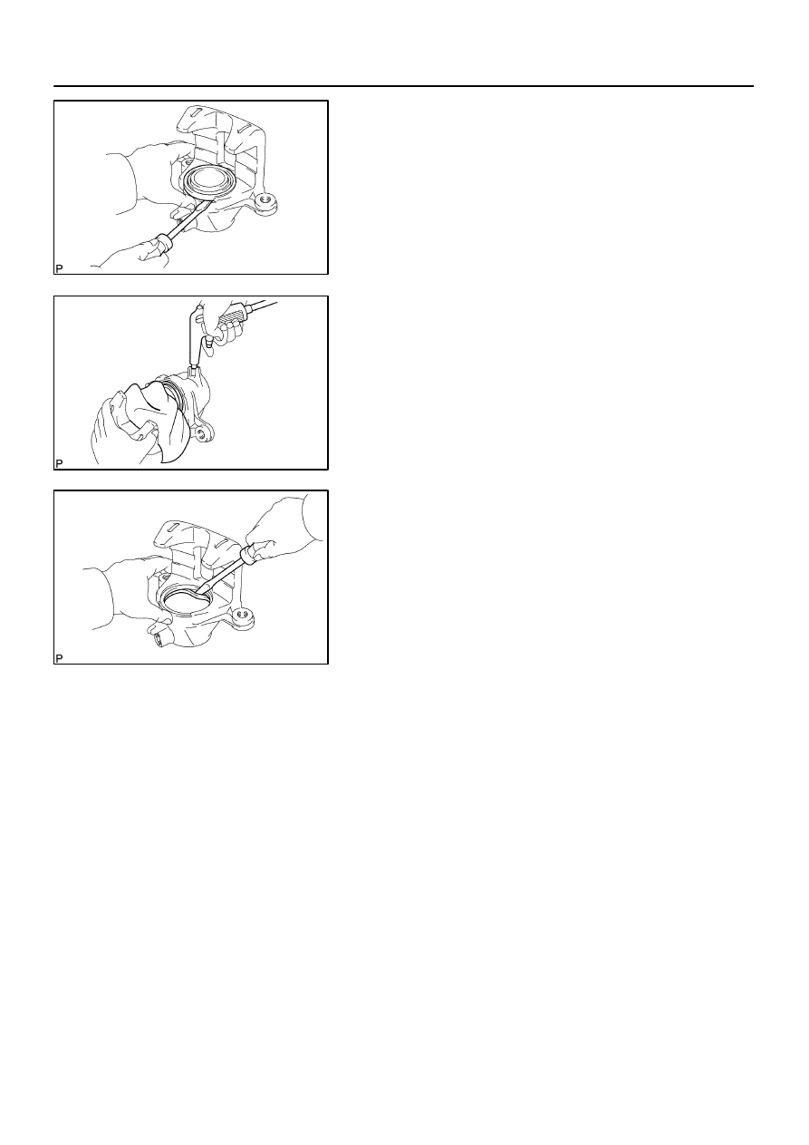
DISASSEMBLY
1.
REMOVE CYLINDER BOOTS
Using a screwdriver, remove the cylinder boot from the caliper.
2.
REMOVE PISTON
(a)
Place a piece of cloth or a similar object between the pis-
ton and caliper.
(b)
Use compressed air to remove the piston from the cylin-
der.
CAUTION:
Do not place your fingers in front of the piston when using
compressed air.
3.
REMOVE PISTON SEAL FROM BRAKE CYLINDER
Using a screwdriver, remove the piston seal from the caliper.
4.
REMOVE CAP AND BLEEDER PLUG
Torque: 11 N·m (110 kgf·cm, 8 ft·lbf)
5.
REMOVE BUSHING, PLUG AND BOOT
BR0JU–14
F13320
F13321
F13322
–
BRAKE
REAR BRAKE CALIPER
BR–39
3206
INSPECTION
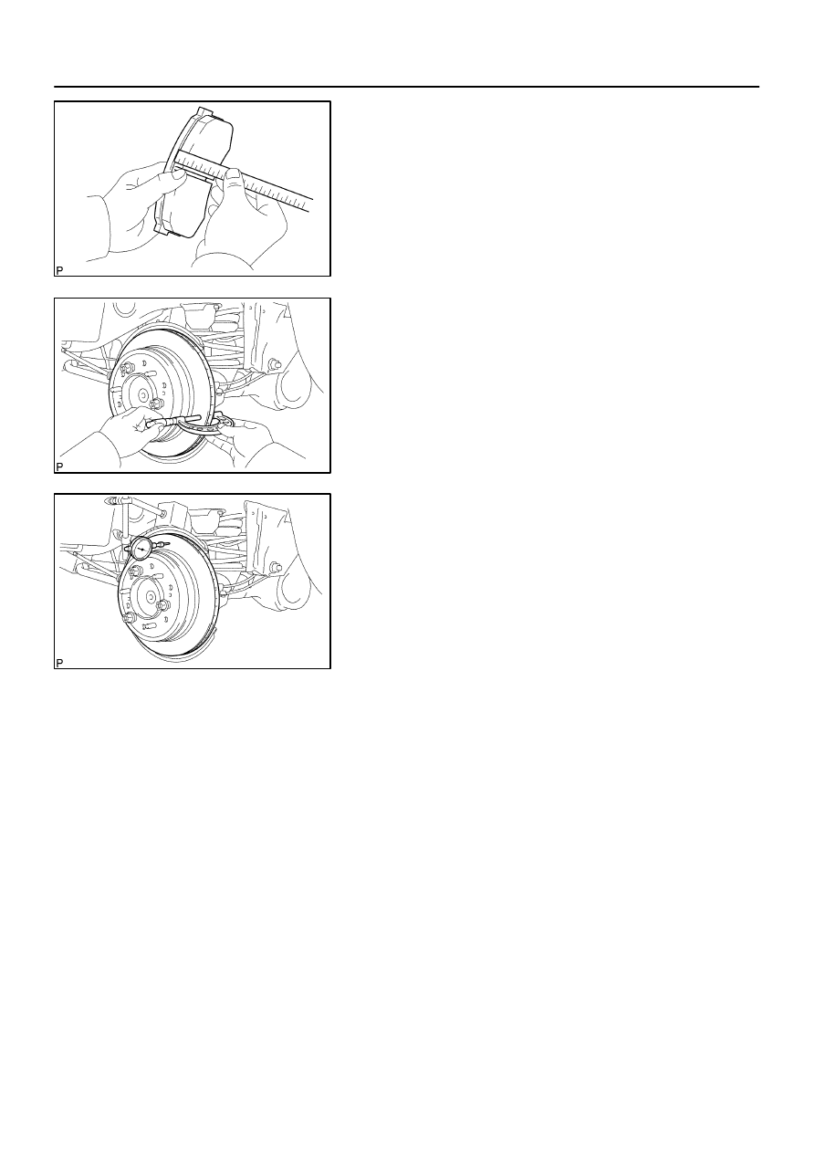
1.
MEASURE PAD LINING THICKNESS
Using a ruler, measure the pad lining thickness.
Standard thickness: 10.0 mm (0.39 in.)
Minimum thickness: 1.0 mm (0.039 in.)
Replace the pad if the pad’s thickness is at the minimum or if
it shows signs of uneven wear.
2.
MEASURE DISC THICKNESS
(a)
Temporarily fasten the disc with the 3 hub nuts.
(b)
Using a micrometer, measure the disc thickness.
Standard thickness: 18.0 mm (0.709 in.)
Minimum thickness: 16.0 mm (0.611 in.)
Replace the disc if the thickness of the disc is at the minimum
thickness or less. Replace the disc or grind it on a lathe if it is
scored or is worn unevenly.
3.
MEASURE DISC RUNOUT
Using a dial indicator, measure the disc runout at a position 10
mm (0.39 in.) from the outside edge.
Maximum disc runout: 0.1 mm (0.0039 in.)
If the disc’s runout is at the maximum value or greater, check the
bearing play is in the axial direction and check the axle hub run-
out (See page
). If the bearing play and axle hub runout
are not abnormal, adjust the disc runout or grind it on an ”On–
Car” brake lathe.
4.
IF NECESSARY, ADJUST DISC RUNOUT
(a)
Remove the 2 bolts and torque plate from the backing
plate.
(b)
Remove the hub nuts and the disc. Reinstall the disc ro-
tating 1/6 of a turn from its original position on the hub.
Install and torque the hub nuts.
Torque: 110 N·m (1,122 kgf·cm, 81 ft·lbf)
Remeasure the disc runout. Make a note of the runout
and the disc’s position on the hub.
(c)
Repeat (b) until the disc has been installed on the 4 re-
maining hub positions.
(d)
If the minimum runout recorded in (b) and (c) is less than
0.1 mm (0.0039 in.), install the disc in that position.
(e)
If the minimum runout recorded in (b) and (c) is greater
than 0.1 mm (0.0039 in.), replace the disc and repeat step
3.
(f)
Install the torque plate and tighten the 2 bolts.
Torque: 105 N·m (1,070 kgf·cm, 77 ft·lbf)
BR0JV–09
BR–40
–
BRAKE
REAR BRAKE CALIPER
3207
REASSEMBLY
Reassembly is in the reverse order of disassembly (See page
HINT:
Apply lithium soap base glycol grease to the parts indicated by the arrows (See page
BR0JW–10
–
BRAKE
REAR BRAKE CALIPER
BR–41
3208
INSTALLATION
Installation is in the reverse order of removal (See page
HINT:
After installation, fill the brake reservoir with brake fluid and bleed brake system (See page
Check for leaks.
Нет комментариевНе стесняйтесь поделиться с нами вашим ценным мнением.
Текст