Toyota Sequoia (2005). Manual — part 142

–
DIAGNOSTICS
ENGINE
DI–363
557
FAIL SAFE
If the ETCS (Electronic Throttle Control System) has a malfunction, the ECM cuts off current to the throttle
control motor. The throttle control valve returns to a predetermined opening angle (approximately 16
°
) by
the force of the return spring. The ECM then adjusts the engine output by controlling the fuel infection (inter-
mittent fuel–cut) and ignition timing in accordance with the accelerator pedal opening angle to enable the
vehicle to continue at a minimum speed.
If the accelerator pedal is depressed firmly and slowly, the vehicle can be driven slowly.
If a ”pass” condition is detected and then the ignition switch is turned OFF, the fail–safe operation will stop
and the system will return to normal condition.
MONITOR STRATEGY
Related DTCs
P2118
Throttle actuator motor power supply line range
check (Low voltage)
Required sensors/components
Throttle actuator motor
Frequency of operation
Continuous
Duration
0.8 sec.
MIL operation
Immediate
Sequence of operation
None
TYPICAL ENABLING CONDITIONS
It
Specification
Item
Minimum
Maximum
The monitor will run whenever this DTC is
not present
See page
Actuator power
ON
Battery voltage
8 V
–
TYPICAL MALFUNCTION THRESHOLDS
Detection Criteria
Threshold
Throttle actuator motor power supply voltage
Less than 4 V
COMPONENT OPERATING RANGE
Parameter
Standard Value
Throttle actuator motor power supply voltage
9 to 14 V
A05652
A18100
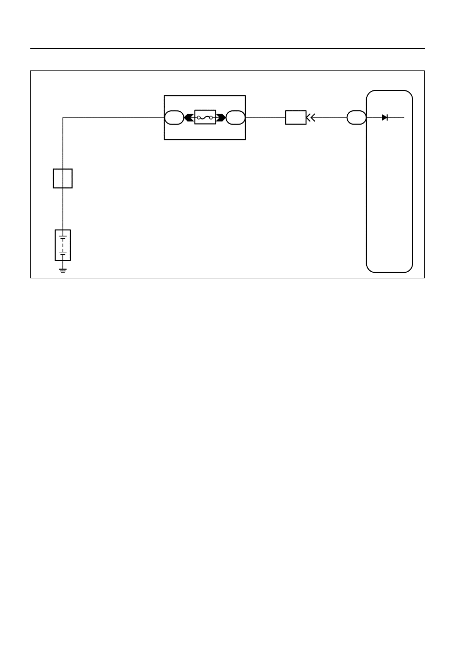
ECM
+BM
E4
7
W–G
Battery
2H
3
ETCS
2D
1
Engine Room J/B
B
IA4
13
W–G
4
F10
Fusible Link
Block
5
B
DI–364
–
DIAGNOSTICS
ENGINE
558
WIRING DIAGRAM
A21380
Engine Room J/B
ETCS
Fuse
B17411
+BM (+)
E6
E4
E1 (–)
–
DIAGNOSTICS
ENGINE
DI–365
559
INSPECTION PROCEDURE
HINT:
Read freeze frame data using
the hand−held tester.
Freeze frame data records the engine conditions when
a malfunction is detected. When troubleshooting, freeze frame data can help determine if the vehicle was
running or stopped, if the engine was warmed up or not, if the air–fuel ratio was lean or rich, as well as other
data from the time when a malfunction occurred.
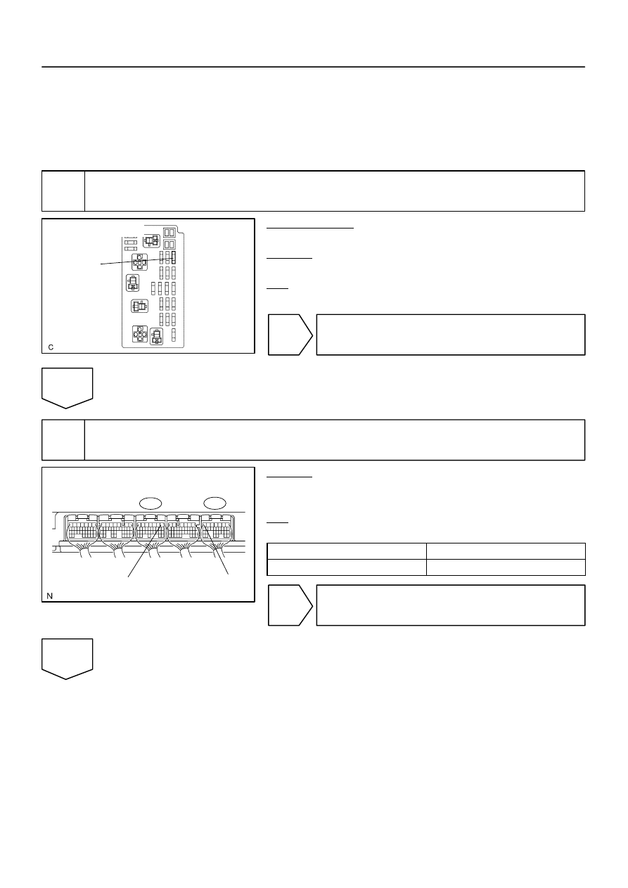
1
Check ETCS fuse.
PREPARATION:
Remove the ETCS fuse from the engine room J/B.
CHECK:
Check the resistance of the ETCS fuse.
OK:
Below 1
Ω
NG
Check for short in all harness and components
connected to ETCS fuse.
OK
2
Check voltage between terminal +BM and E1 of ECM connector.
CHECK:
Measure the voltage between the specified terminals of the E6
and E4 ECM connector.
OK:
Standard:
Tester Connection
Specified Condition
+BM (E4–7) – E6 (E6–1)
9 to 14 V
OK
Check for intermittent problems
(See page
NG
A21380
Engine Room J/B
ETCS
Fuse
B17417
E4
+BM
DI–366
–
DIAGNOSTICS
ENGINE
560
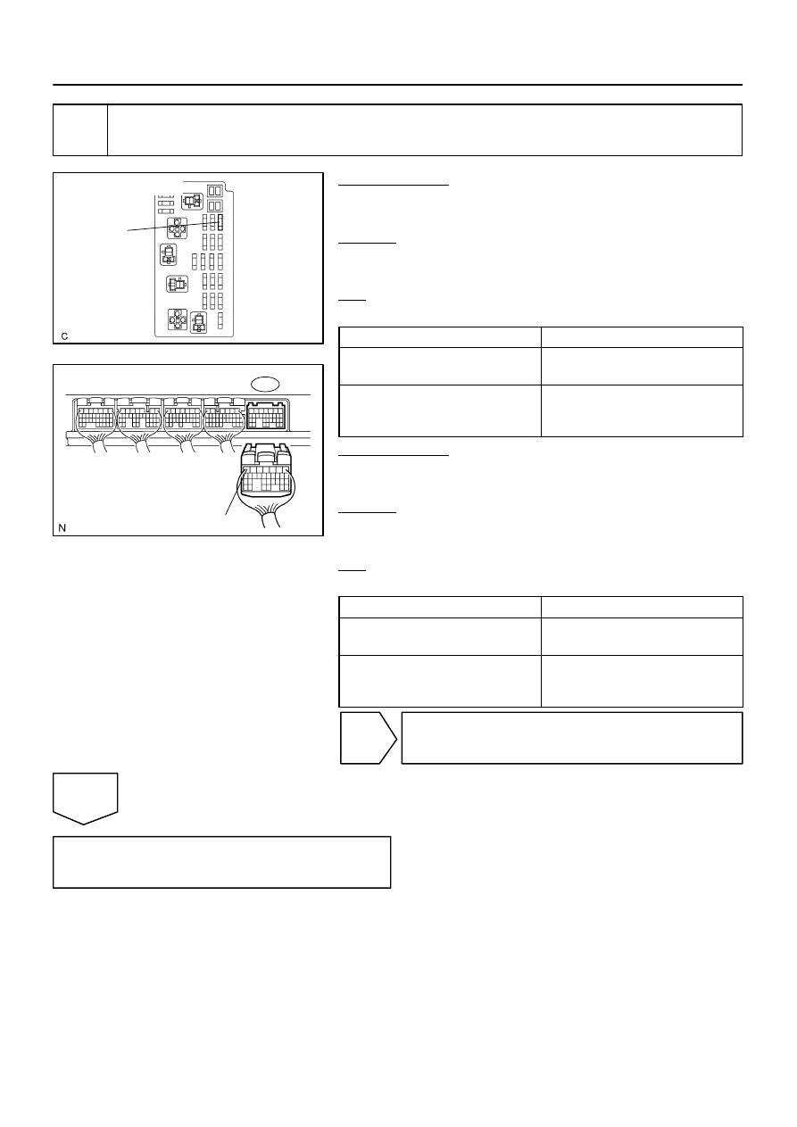
3
Check for open or short in harness or connector between battery and ETCS fuse,
ETCS fuse and ECM.
PREPARATION:
(a)
Remove the ETCS fuse from the engine room J/B.
(b)
Disconnect the E4 ECM connector.
CHECK:
Measure the resistance of the wire harness side connector be-
tween the ETCS fuse and ECM.
OK:
Standard:
Tester Connection
Specified Condition
Engine Room J/B (ETCS fuse
terminal) – +BM (E4–7)
Below 1
Ω
Engine Room J/B (ETCS fuse
terminal) or +BM (E4–7) –
Body ground
10 k
Ω
or higher
PREPARATION:
(a)
Remove the ETCS fuse from the engine room J/B.
(b)
Disconnect the battery positive terminal.
CHECK:
Measure the resistance of the wire harness side connector be-
tween the ETCS fuse and battery.
OK:
Standard:
Tester Connection
Specified Condition
Engine Room J/B (ETCS fuse
terminal) – Battery positive terminal
Below 1
Ω
Engine Room J/B (ETCS fuse
terminal) or
Battery positive terminal – Body ground
10 k
Ω
or higher
NG
Repair or replace harness or connector.
OK
Check engine room J/B.
Нет комментариевНе стесняйтесь поделиться с нами вашим ценным мнением.
Текст