Toyota Sequoia (2005). Manual — part 140

–
DIAGNOSTICS
ENGINE
DI–355
549
MONITOR STRATEGY
R l t d DTC
P2102
Throttle actuator control motor current
(Low current)
Related DTCs
P2103
Throttle actuator control motor current
(High current)
Required sensors/components
Throttle actuator motor
Frequency of operation
Continuous
Duration
2 sec.
MIL operation
Immediate
Sequence of operation
None
TYPICAL ENABLING CONDITIONS
It
Specification
Item
Minimum
Maximum
The monitor will run whenever these
DTCs are not present
See page
P2102:
Throttle motor
ON
Duty–cycle ratio to open throttle actuator
80%
–
Throttle actuator power supply
8 V
–
Current motor current – Motor current at
0.016 sec. before
–
0.2 A
P2103:
Throttle motor
ON
Either of the following conditions is met:
Condition 1 or 2
1. Throttle actuator power supply
8 V
–
2. Throttle actuator power
ON
Battery voltage
8 V
–
Starter
OFF
TYPICAL MALFUNCTION THRESHOLDS
Detection Criteria
Threshold
P2102:
Throttle motor current
Less than 0.5 A (when motor drive duty 80% or more)
P2103:
Throttle motor current
More than 10 A (0.1 sec.)
More than 7 A (0.6 sec.)
WIRING DIAGRAM
Refer to DTC P0120 on page
.
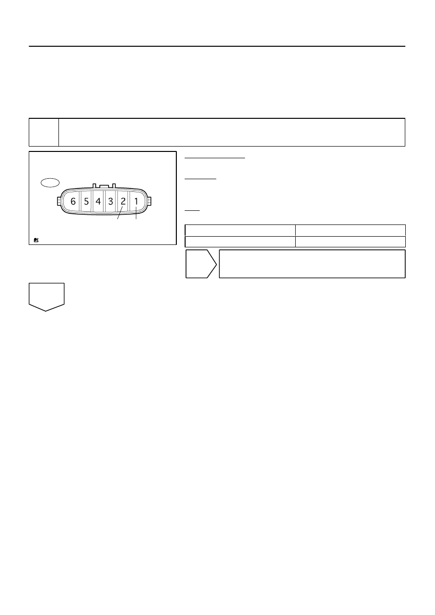
A21034
T14
Component Side:
M+
M–
Throttle Control Motor and Sensor
DI–356
–
DIAGNOSTICS
ENGINE
550
INSPECTION PROCEDURE
HINT:
Read freeze frame data using
the hand−held tester
. Freeze frame data records the engine conditions when
a malfunction is detected. When troubleshooting, freeze frame data can help determine if the vehicle was
running or stopped, if the engine was warmed up or not, if the air–fuel ratio was lean or rich, as well as other
data from the time when a malfunction occurred.
1
Check throttle control motor.
PREPARATION:
Disconnect the throttle control motor and sensor connector.
CHECK:
Measure the resistance between terminals of the throttle con-
trol motor.
OK:
Standard:
Tester Connection
Specified Condition
M+ (T14–2) – M– (T14–1)
0.3 to100
Ω
(20
°
C (68
°
F))
NG
Replace throttle body (See page
OK
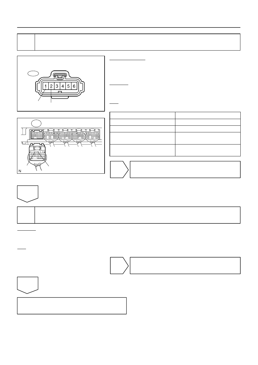
A21022
T14
M+
M–
Wire Harness Side:
Throttle Control Motor and Sensor
B17412
M+
M–
E8
ECM Connector
–
DIAGNOSTICS
ENGINE
DI–357
551
2
Check for open and short in harness and connector between throttle control mo-
tor and ECM.
PREPARATION:
(a)
Disconnect the T14 throttle control motor and sensor con-
nector.
(b)
Disconnect the E8 ECM connector.
CHECK:
Measure the resistance between the wire harness side connec-
tors.
OK:
Standard:
Tester Connection
Specified Condition
M+ (T14–2) – M+ (E8–3)
Below 1
Ω
M– (T14–1) – M– (E8–2)
Below 1
Ω
M+ (T14–2) or M+ (E8–3) –
Body ground
10 k
Ω
or higher
M– (T14–1) or M– (E8–2) –
Body ground
10 k
Ω
or higher
NG
Repair or replace harness or connector.
OK
3
Visually check throttle valve.
CHECK:
Check the area between the throttle valve and the housing for foreign objects.
Also, check if the valve can open and close smoothly.
OK:
The throttle valve is not contaminated by foreign objects and can move smoothly.
NG
Remove foreign object and clean throttle body.
OK
Replace ECM (See page

DI–358
–
DIAGNOSTICS
ENGINE
552
DTC
P2111
Throttle Actuator Control System
–Stuck Open
DTC
P2112
Throttle Actuator Control System
–Stuck Closed
CIRCUIT DESCRIPTION
The throttle motor is operated by the ECM. It opens and closes the throttle valve using gears. The opening
angle of the throttle valve is detected by the throttle position sensor, which is mounted on the throttle body.
The throttle position sensor provides feedback to the ECM to control the throttle motor and set the throttle
valve angle in response to driver input.
HINT:
This Electrical Throttle Control System (ETCS) does not use a throttle cable.
DTC No.
DTC Detection Condition
Trouble Area
P2111
Throttle motor locked during ECM order to close.
(1 trip detection logic)
Throttle control motor and sensor circuit
Throttle control motor and sensor
P2112
Throttle motor locked during ECM order to open.
(1 trip detection logic)
Throttle control motor and sensor
Throttle body
Throttle valve
MONITOR DESCRIPTION
The ECM concludes that there is a malfunction of the ETCS (Electronic Throttle Control System) when the
throttle valve remains at a fixed angle despite high drive current from the ECM. The ECM will turn on the MIL
and a DTC is set.
FAIL SAFE
If the ETCS (Electronic Throttle Control System) has a malfunction, the ECM cuts off current to the throttle
control motor. The throttle control valve returns to a predetermined opening angle (approximately 16
°
) by
the force of the return spring. The ECM then adjusts the engine output by controlling the fuel infection (inter-
mittent fuel–cut) and ignition timing in accordance with the accelerator pedal opening angle to enable the
vehicle to continue at a minimum speed.
If the accelerator pedal is depressed firmly and slowly, the vehicle can be driven slowly.
If a ”pass” condition is detected and then the ignition switch is turned OFF, the fail–safe operation will stop
and the system will return to normal condition.
DICFA–02
Нет комментариевНе стесняйтесь поделиться с нами вашим ценным мнением.
Текст