Toyota Sequoia (2005). Manual — part 143

–
DIAGNOSTICS
ENGINE
DI–367
561
DTC
P2119
Throttle Actuator Control Throttle Body
Range/Performance
CIRCUIT DESCRIPTION
The Electric Throttle Control System (ETCS) is composed of a throttle motor that operates the throttle valve,
a throttle position sensor that detects the opening angle of the throttle valve, an accelerator pedal position
sensor that detects the accelerator pedal position, and the ECM that controls the ETCS system.
The ECM operates the throttle motor to position the throttle valve for proper response to driver inputs. The
throttle position sensor, mounted on the throttle body, detects the opening angle of the throttle valve and
provides this signal to the ECM so that the ECM can regulate the throttle motor.
DTC No.
DTC Detection Condition
Trouble Area
P2119
Throttle opening angle continues to vary greatly from target
throttle opening angle
(1 trip detection logic)
Electric throttle control system
Throttle body
MONITOR DESCRIPTION
The ECM determines the ”actual” throttle angle based on the throttle position sensor signal. The ”actual”
throttle position is compared to the ”target” throttle position commanded by the ECM. If the difference of
these two values exceeds a specified limit, the ECM interprets this as a fault in the ETCS (Electronic Throttle
Control System). The ECM turns on the MIL and a DTC is set.
FAIL SAFE
If the ETCS (Electronic Throttle Control System) has a malfunction, the ECM cuts off current to the throttle
control motor. The throttle control valve returns to a predetermined opening angle (approximately 16
°
) by
the force of the return spring. The ECM then adjusts the engine output by controlling the fuel infection (inter-
mittent fuel–cut) and ignition timing in accordance with the accelerator pedal opening angle to enable the
vehicle to continue at a minimum speed.
If the accelerator pedal is depressed firmly and slowly, the vehicle can be driven slowly.
If a ”pass” condition is detected and then the ignition switch is turned OFF, the fail–safe operation will stop
and the system will return to normal condition.
MONITOR STRATEGY
Related DTCs
P2119
Electronic throttle control system failure
R
i d
/
t
Main sensors
Throttle actuator motor
Required sensors/components
Related sensors
Throttle position sensor
Frequency of operation
Continuous
Duration
1 sec.
MIL operation
Immediate
Sequence of operation
None
TYPICAL ENABLING CONDITIONS
The monitor will run whenever this DTC is
not present
See page
The typical enabling condition is not avail-
able
–
DICFC–02

DI–368
–
DIAGNOSTICS
ENGINE
562
TYPICAL MALFUNCTION THRESHOLDS
Detection Criteria
Threshold
Difference between ”target throttle position” and ”actual
throttle position”
0.3 V or more
COMPONENT OPERATING RANGE
Standard Value
Commanded throttle position and current throttle position are nearly the same
WIRING DIAGRAM
Refer to DTC P2102 and P2103 on page
INSPECTION PROCEDURE
HINT:
Read freeze frame data using
the hand−held tester
. Freeze frame data records the engine conditions when
a malfunction is detected. When troubleshooting, freeze frame data can help determine if the vehicle was
running or stopped, if the engine was warmed up or not, if the air–fuel ratio was lean or rich, as well as other
data from the time when a malfunction occurred.
1
Are there any other codes (besides DTC P2119) being output?
PREPARATION:
(a)
Connect the hand–held tester to the DLC3.
(b)
Turn the ignition switch ON and push the hand–held tester main switch ON.
(c)
When using hand–held tester, enter the following menu: DIAGNOSIS / ENHANCED OBD II / DTC
INFO / CURRENT CODES.
CHECK:
Read the DTC using the hand–held tester.
RESULT:
Display (DTC Output)
Proceed to
P2119
A
”P2119” and other DTC
B
HINT:
If any other codes besides P2119 are output, perform the troubleshooting for those DTCs first.
B
Go to relevant DTC chart (See page
A
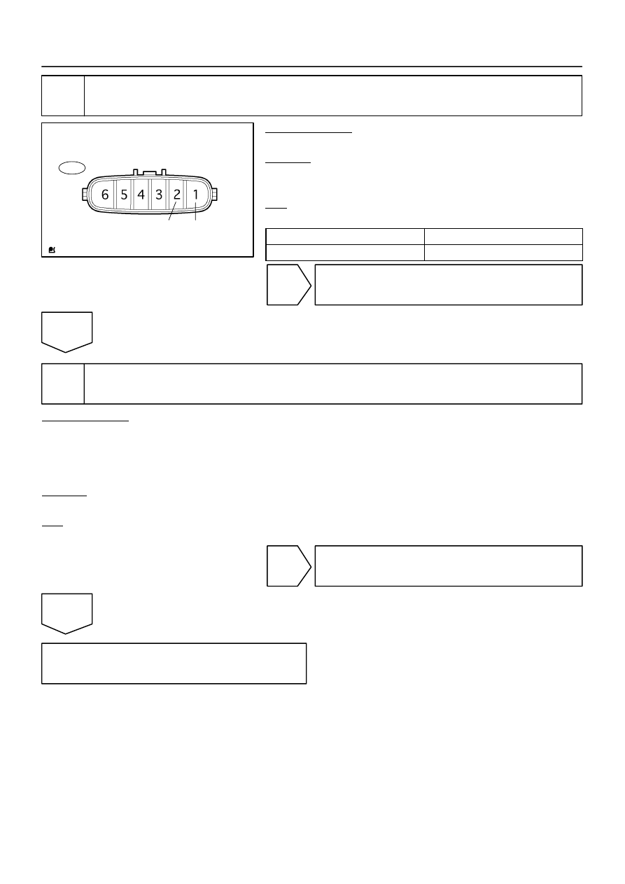
A21034
T14
Component Side:
M+
M–
Throttle Control Motor and Sensor
–
DIAGNOSTICS
ENGINE
DI–369
563
2
Check throttle control motor.
PREPARATION:
Disconnect the throttle control motor and sensor connector.
CHECK:
Measure the resistance between terminals of the throttle con-
trol motor.
OK:
Standard:
Tester Connection
Specified Condition
M+ (T14–2) – M– (T14–1)
0.3 to100
Ω
(20
°
C (68
°
F))
NG
Replace throttle body (See page
OK
3
Replace ECM and check DTC (Check if DTC outputs reoccur).
PREPARATION:
(a)
Replace ECM.
(b)
).
(c)
Start and warm up the engine.
(d)
Run the engine at idle for 15 seconds or more.
CHECK:
Read the DTC using the hand–held tester (See page
).
OK:
No DTC output.
OK
System is normal.
NG
Replace throttle body.

DI–370
–
DIAGNOSTICS
ENGINE
564
DTC
P2120
Throttle/Pedal Position Sensor/Switch ”D”
Circuit
DTC
P2122
Throttle/Pedal Position Sensor/Switch ”D”
Circuit Low Input
DTC
P2123
Throttle/Pedal Position Sensor/Switch ”D”
Circuit High Input
DTC
P2125
Throttle/Pedal Position Sensor/Switch ”E”
Circuit
DTC
P2127
Throttle/Pedal Position Sensor/Switch ”E”
Circuit Low Input
DTC
P2128
Throttle/Pedal Position Sensor/Switch ”E”
Circuit High Input
DTC
P2138
Throttle/Pedal Position Sensor/Switch
”D”/”E” Voltage Correlation
HINT:
This is the repair procedure for the ”accelerator pedal position sensor”.
DID8G–01
Нет комментариевНе стесняйтесь поделиться с нами вашим ценным мнением.
Текст