Toyota Sequoia (2005). Manual — part 896
H05544
H16661
H16662
H16663
BO–20
–
BODY
REAR DOOR
3573
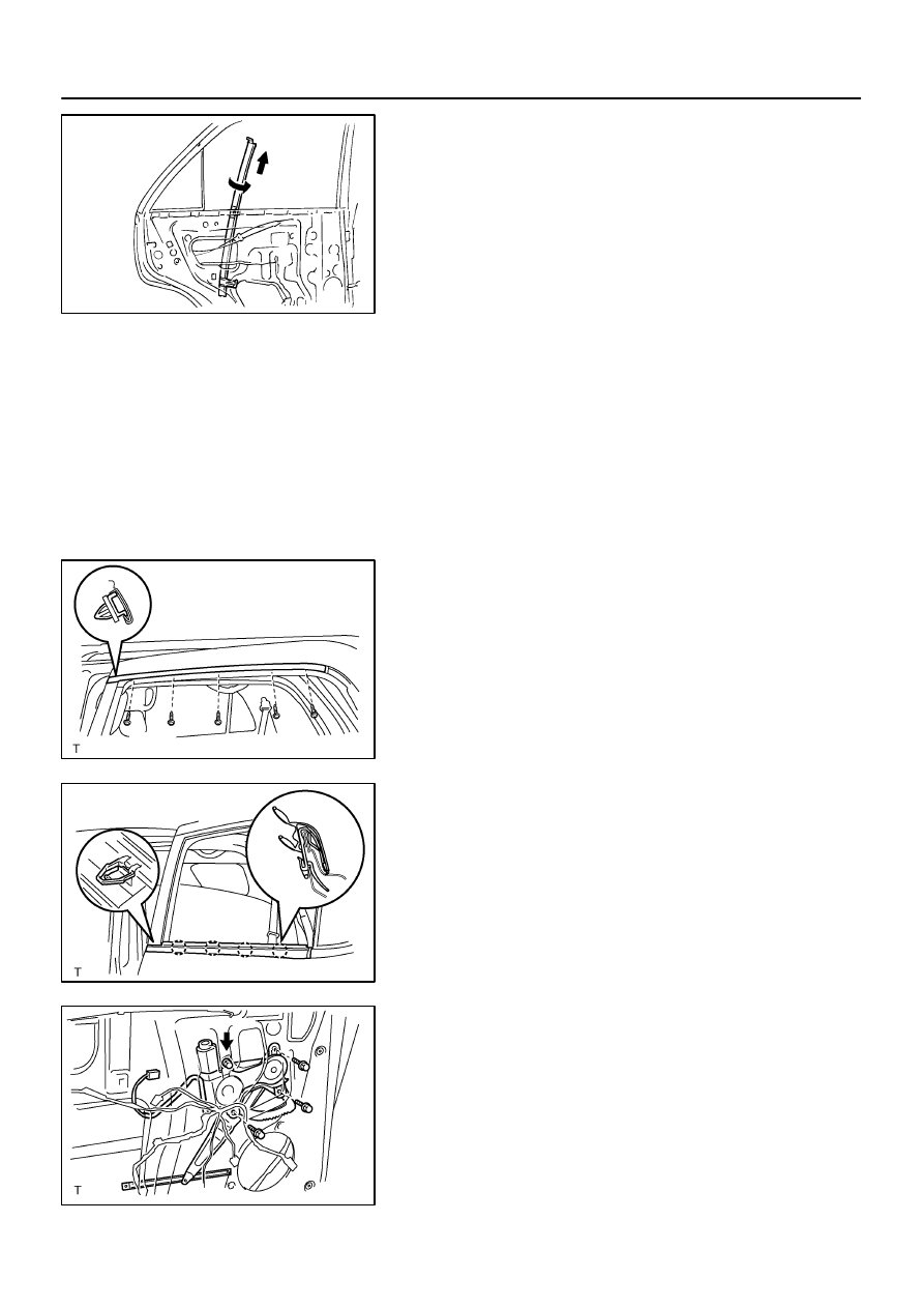
(g)
Rotate the division bar 90
°
and pull it upward as shown
in the illustration.
9.
REMOVE REAR DOOR QUARTER WINDOW GLASS
(a)
Remove the rear door quarter window glass.
NOTICE:
Do not damage the glass.
(b)
Remove the quarter window weatherstrip from the glass.
10.
REMOVE DOOR GLASS
Pull the glass up out of the panel carefully.
HINT:
Insert a shop rag inside the panel to prevent scratching the
glass.
11.
REMOVE UPPER WINDOW FRAME MOULDING
(a)
Remove the 5 screws.
(b)
Using a screwdriver or clip remover, remove the upper
window frame moulding.
HINT:
Tape the screwdriver tip before use.
12.
REMOVE DOOR BELT MOULDING
(a)
Apply protective tape to the outer surface as shown in the
illustration, to keep the surface from being scratched.
(b)
Using a moulding remover, remove the door belt mould-
ing.
13.
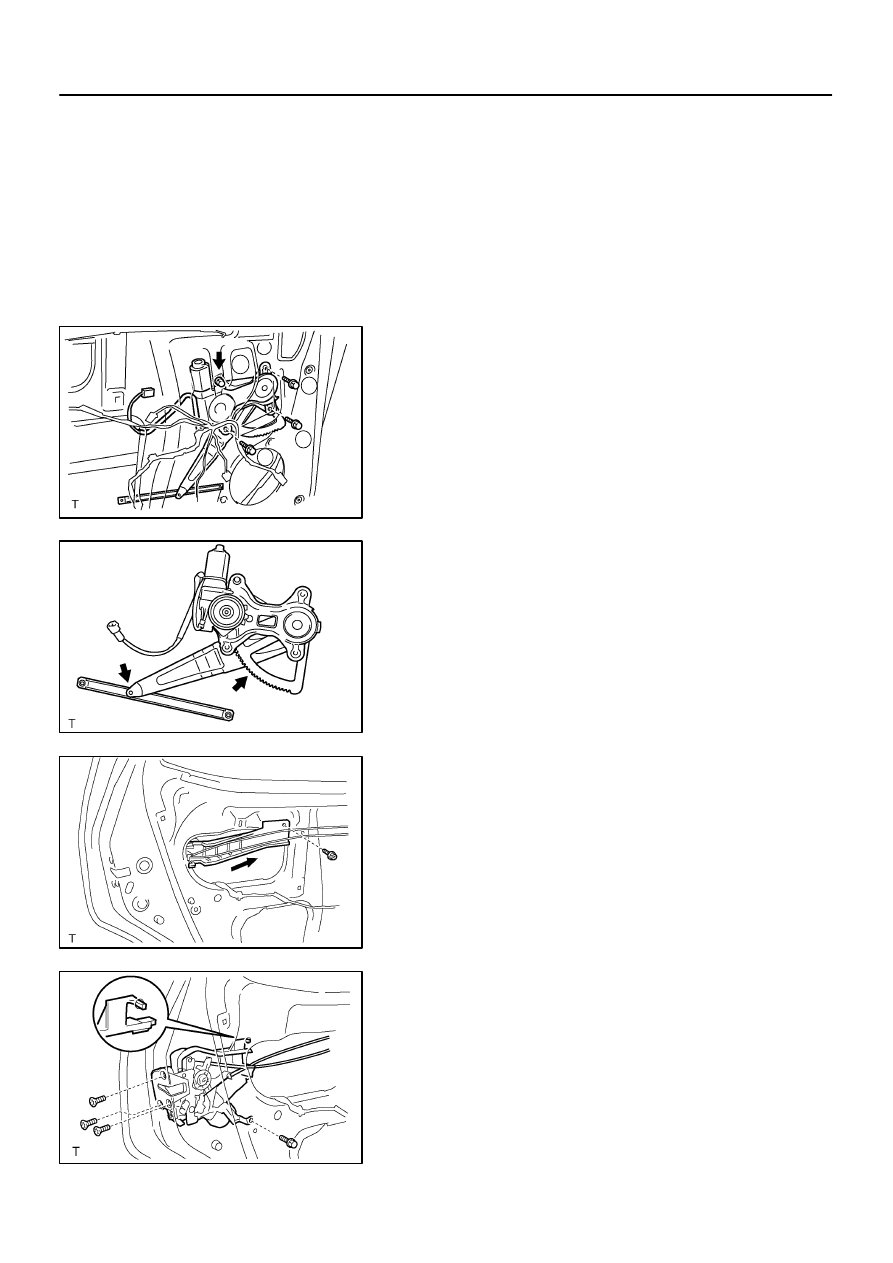
REMOVE WINDOW REGULATOR ASSEMBLY
(a)
Disconnect the connector.
(b)
Remove the 3 bolts.
Torque: 8.0 N·m (82 kgf·cm, 71 in.·lbf)
(c)
Loosen the bolt, then remove the window regulator as-
sembly.
Torque: 8.0 N·m (82 kgf·cm, 71 in.·lbf)
HINT:
Remove the window regulator assembly through the service
hole.
H16663
1
3
2
4
4
H16664
H16665
H16666
–
BODY
REAR DOOR
BO–21
3574
(d)
Remove the 3 screws and window regulator motor from
the window regulator sub–assembly.
HINT:
At the time of reassembly, please refer to the following items.
Tighten the bolts in the order shown in the illustration.
Apply MP grease to the window regulator assembly.
NOTICE:
At the time of reassembly, please refer to the following
item.
Do not apply grease to the spring of the window regulator
assembly.
14.
REMOVE DOOR LOCK
(a)
Disengage the 2 control cables from the clamp.
(b)
Remove the clamp.
(c)
Remove the screw and cable protector.
(d)
Disconnect the connector.
(e)
Remove the bolt, 3 screws and door lock.
HINT:
Remove the door lock through the service hole.
Torque:
Bolt: 5.0 N·m (51 kgf·cm, 44 in.·lbf)
Screw: 5.5 N·m (56 kgf·cm, 49 in.·lbf)
H16667
BO–22
–
BODY
REAR DOOR
3575
HINT:
At the time of reassembly, please refer to the following
items.
Apply adhesive to 3 screws.
Part No. 08833–00070, THREE BOND 1324 or equiva-
lent.
Install the door lock as shown in the illustration.
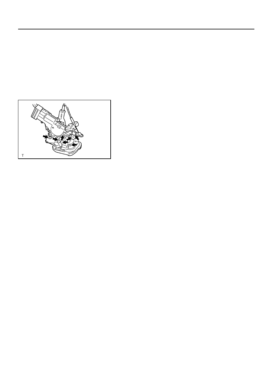
(f)
Remove the 2 screws and door lock outer cover from the
door lock.
HINT:
At the time of reassembly, please refer to the following item.
Apply MP grease to the sliding and rotating part of the door lock.
15.
REMOVE OUTSIDE HANDLE
Torque: 5.5 N·m (56 kgf·cm, 49 in.·lbf)
16.
REMOVE REAR DOOR WEATHERSTRIP
17.
REMOVE REAR DOOR OUTSIDE LOWER MOULDING
18.
REMOVE NO. 2 REAR DOOR WEATHERSTRIP
BO45R–01
H16668
H16669
BO2556
–
BODY
REAR DOOR
BO–23
3576
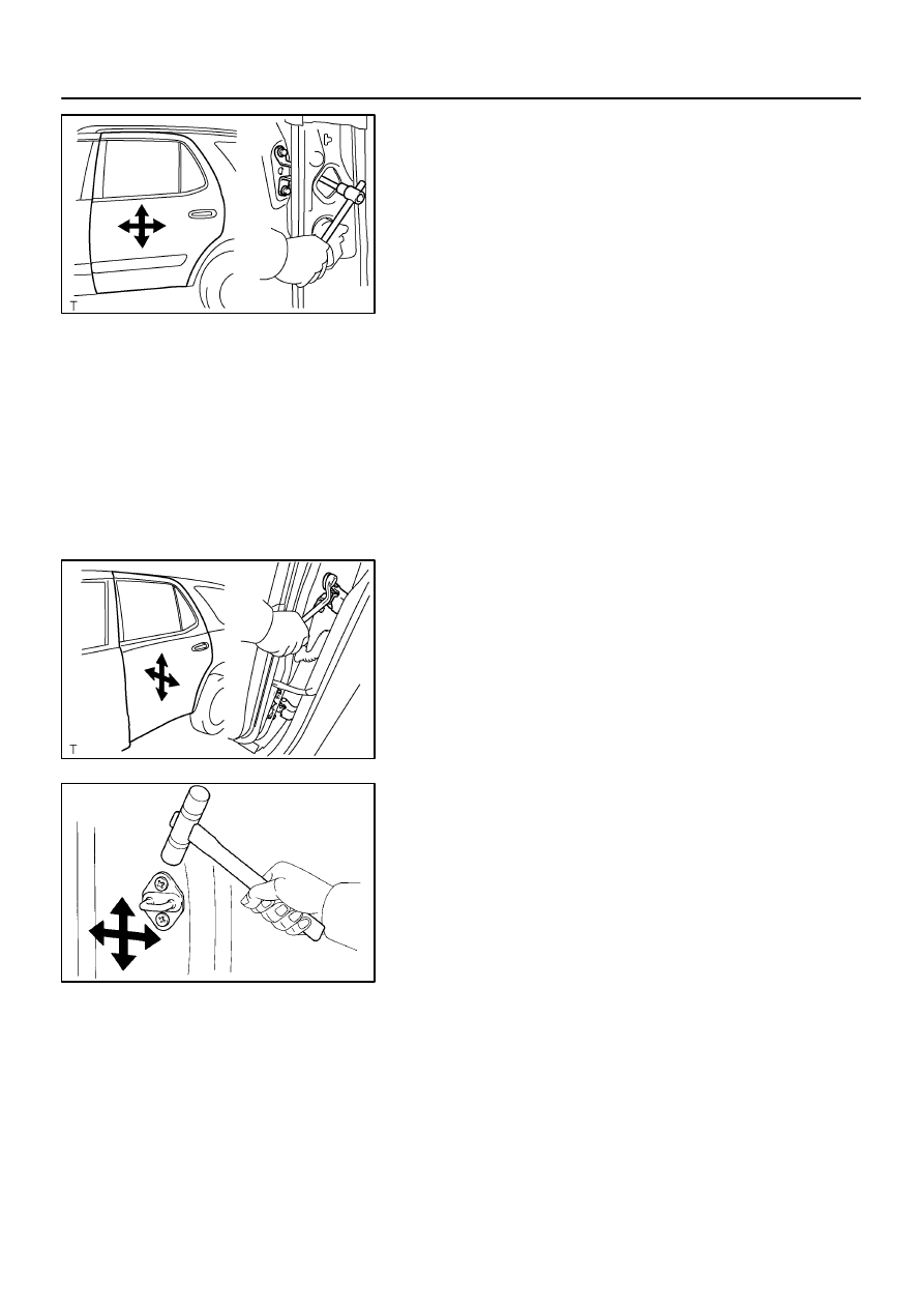
ADJUSTMENT
1.
ADJUST DOOR IN FORWARD/ REARWARD AND VER-
TICAL DIRECTIONS
(a)
Remove the front and rear door scuff plates.
(b)
Remove the center pillar lower garnish.
(c)
Remove the front seat outer belt (See page
(d)
Loosen the body side hinge nuts to adjust.
Torque: 23 N·m (230 kgf·cm, 17 ft·lbf)
(e)
Install the front seat outer belt and center pillar lower gar-
nish (See page
).
(f)
Install the front and rear door scuff plates.
2.
ADJUST DOOR IN LEFT/RIGHT AND VERTICAL
DIRECTIONS
Loosen the door side hinge bolts to adjust.
Torque: 23 N·m (230 kgf·cm, 17 ft·lbf)
3.
ADJUST DOOR LOCK STRIKER
(a)
Check that the door fit and door lock linkages are adjusted
correctly.
(b)
Loosen the striker mounting screws to adjust.
Torque: 23 N·m (230 kgf·cm, 17 ft·lbf)
(c)
Using a plastic hammer, tap the striker to adjust it.
Нет комментариевНе стесняйтесь поделиться с нами вашим ценным мнением.
Текст