Toyota Sequoia (2005). Manual — part 894
H16647
4 Clips
H16648
H16649
H16650
H16651
BO–12
–
BODY
FRONT DOOR
3565
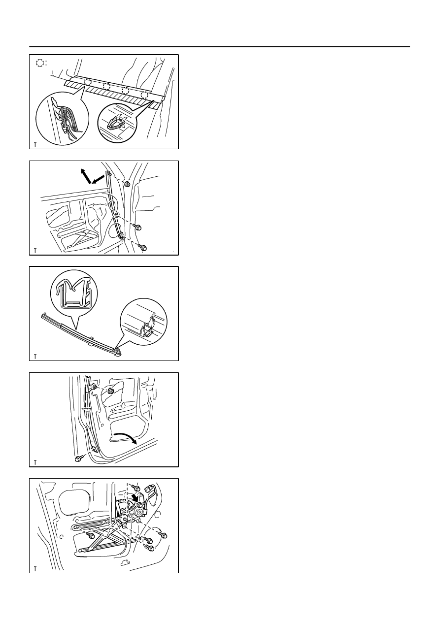
14.
REMOVE DOOR BELT MOULDING
(a)
Apply protective tape to the outer surface as shown in the
illustration, to keep the surface from being scratched.
(b)
Using a moulding remover, remove the door belt mould-
ing.
15.
REMOVE FRONT LOWER FRAME
(a)
Remove the 2 bolts, nut and front lower frame as shown
in the illustration.
(b)
Remove the No. 2 glass run from the front lower frame.
HINT:
At the time of reassembly, please refer to the following item.
Install the No. 2 glass run to the front lower frame as shown in
the illustration.
16.
REMOVE REAR LOWER FRAME
Remove the bolt, nut and rear lower frame as shown in the il-
lustration.
HINT:
Remove the rear lower frame through the service hole.
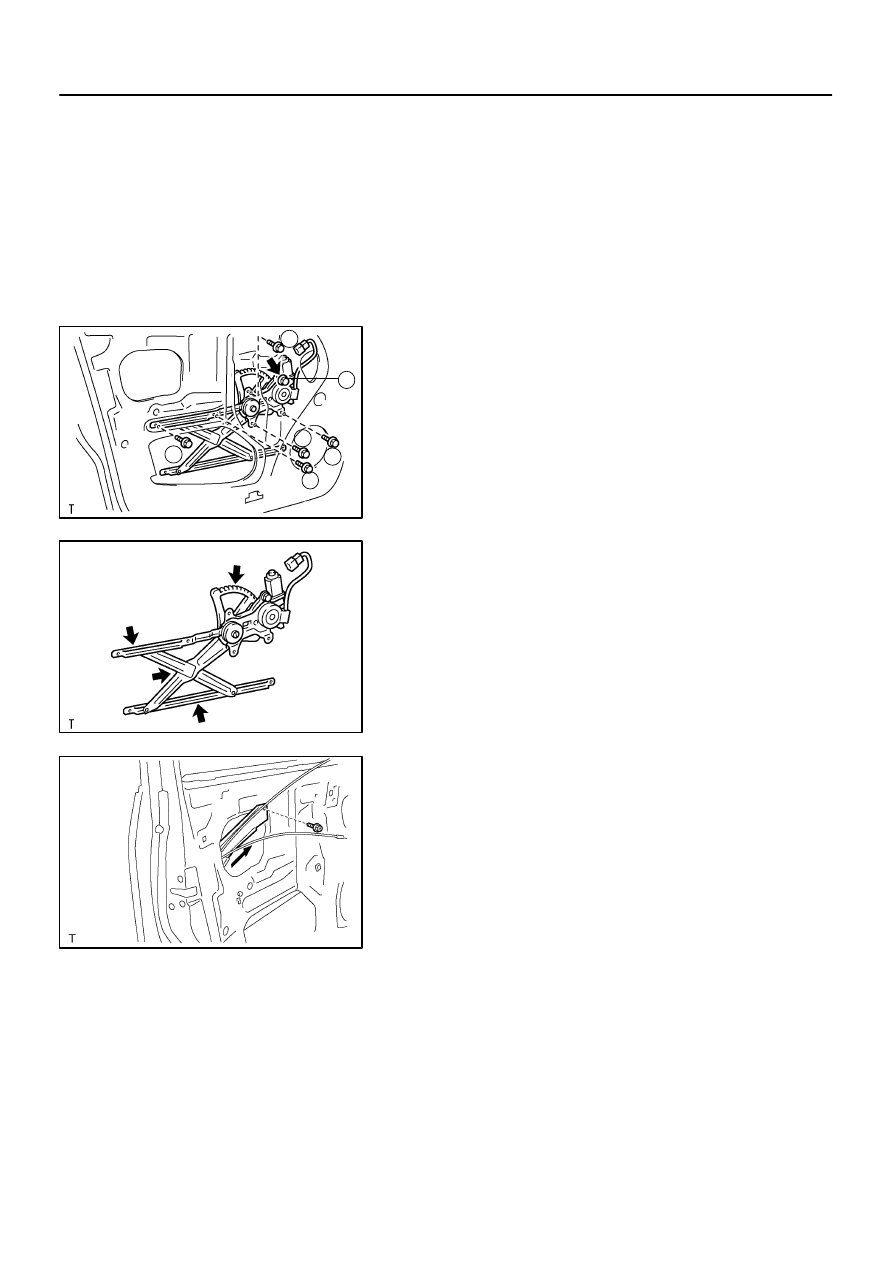
17.
REMOVE WINDOW REGULATOR ASSEMBLY
(a)
Disconnect the connector.
(b)
Remove the 5 bolts.
Torque: 8.0 N·m (82 kgf·cm, 71 in.·lbf)
(c)
Loosen the bolt, then remove the window regulator as-
sembly.
Torque: 8.0 N·m (82 kgf·cm, 71 in.·lbf)
HINT:
Remove the window regulator assembly through the service
hole.
H16651
1
2
3
5
6
4
H16652
H16653
–
BODY
FRONT DOOR
BO–13
3566
(d)
Remove the 3 screws and window regulator motor from
the window regulator sub–assembly.
HINT:
At the time of reassembly, please refer to the following items.
Tighten the bolts in the order shown in the illustration.
Apply MP grease to the window regulator assembly.
NOTICE:
At the time of reassembly, please refer to the following
item.
Do not apply grease to the spring of the window regulator
assembly.
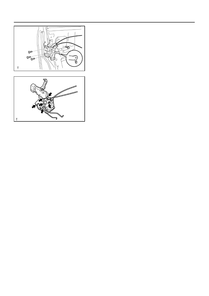
18.
REMOVE DOOR LOCK
(a)
Disengage the 2 control cables from the clamp.
(b)
Remove the clamp.
(c)
Remove the screw and cable protector.
(d)
Disconnect the 2 control links from the outside handle and
lock cylinder.
(e)
Disconnect the connector.
(f)
Remove the bolt, 3 screws and door lock.
HINT:
Remove the door lock through the service hole.
Torque:
Bolt: 5.0 N·m (51 kgf·cm, 44 in.·lbf)
Screw: 5.0 N·m (51 kgf·cm, 44 in.·lbf)
HINT:
At the time of reassembly, please refer to the following
items.
Apply adhesive to 3 screws.
Part No. 08833–00070, THREE BOND 1324 or equiva-
lent.
H16654
H16655
BO–14
–
BODY
FRONT DOOR
3567
Install the door lock as shown in the illustration.
(g)
Remove the 2 screws and door lock outer cover from the
door lock.
HINT:
At the time of reassembly, please refer to the following item.
Apply MP grease to the sliding and rotating parts of the door
lock.
19.
REMOVE OUTSIDE HANDLE WITH LOCK CYLINDER
(a)
Remove the service hole plug.
(b)
Remove the 2 bolts and outside handle with lock cylinder.
Torque: 5.5 N·m (56 kgf·cm, 49 in.·lbf)
(c)
Remove the bolt and lock cylinder from the outside han-
dle.
Torque: 5.5 N·m (56 kgf·cm, 49 in.·lbf)
20.
REMOVE FRONT DOOR WEATHERSTRIP
Using a clip remover, remove the front door weatherstrip.
21.
REMOVE NO. 2 FRONT DOOR WEATHERSTRIP
BO45N–01
H16657
H16658
Z06435
–
BODY
FRONT DOOR
BO–15
3568
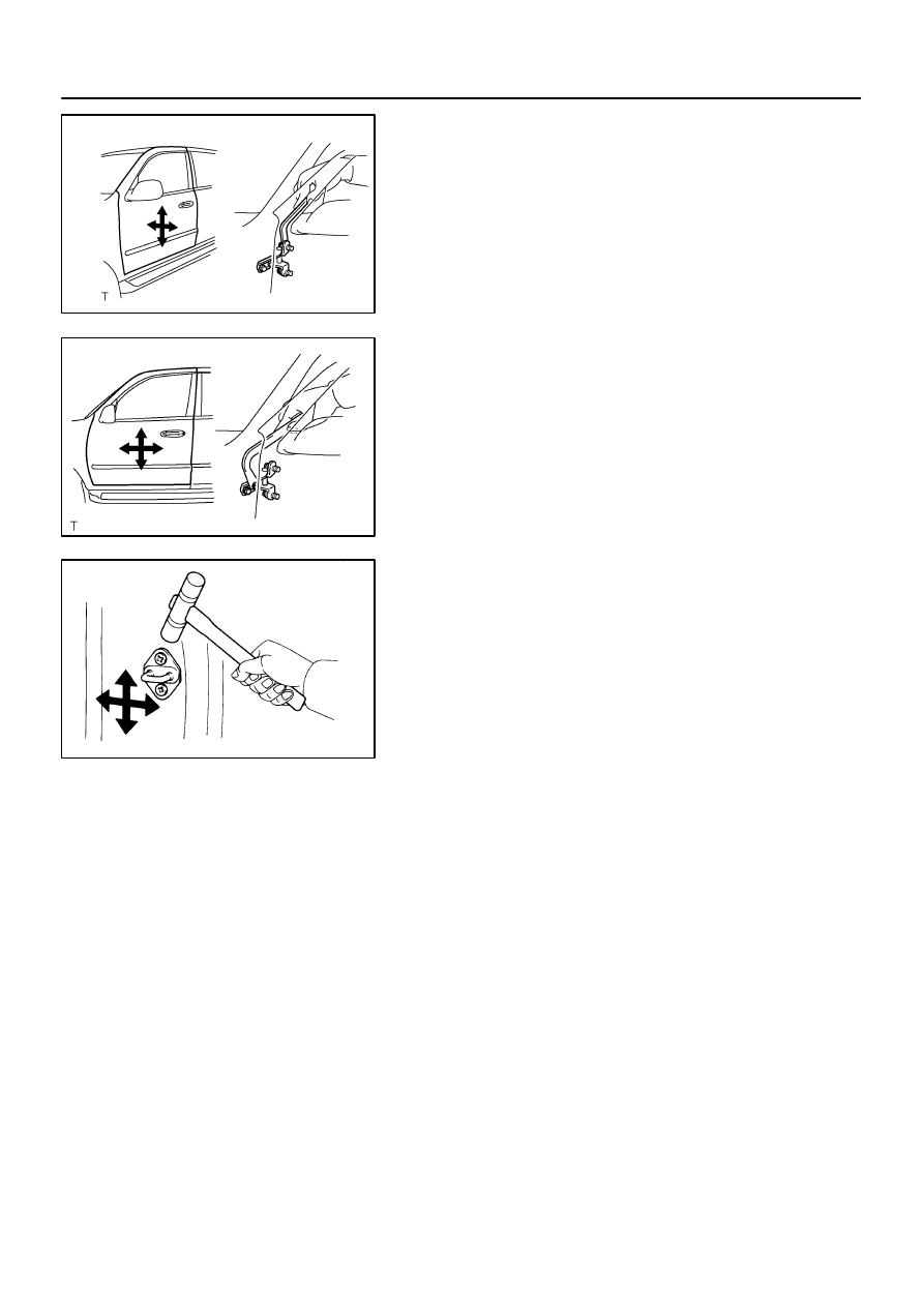
ADJUSTMENT
1.
ADJUST DOOR IN FORWARD/REARWARD AND VER-
TICAL DIRECTIONS
Using SST, adjust the door by loosening the body side hinge
bolts.
SST
09812–00010
Torque: 23 N·m (235 kgf·cm, 17 ft·lbf)
2.
ADJUST DOOR IN LEFT/RIGHT AND VERTICAL
DIRECTIONS
Adjust the door by loosening the door side hinge bolts.
HINT:
Substitute the standard bolt for the centering bolts.
(See page
)
Torque: 23 N·m (235 kgf·cm, 17 ft·lbf)
3.
ADJUST DOOR LOCK STRIKER
(a)
Check that the door fit and door lock linkages are adjusted
correctly.
(b)
Adjust the striker position by slightly loosening the striker
mounting screws, and hitting the striker with a hammer.
(c)
Tighten the striker mounting screws again.
Torque: 23 N·m (235 kgf·cm, 17 ft·lbf)
Нет комментариевНе стесняйтесь поделиться с нами вашим ценным мнением.
Текст