Toyota Sequoia (2005). Manual — part 294

–
DIAGNOSTICS
ABS WITH EBD & BA & TRAC & VSC SYSTEM
DI–971
1165
DTC
C1311 / 12
Open or Short Circuit in Brake Inhibit
Relay Circuit
CIRCUIT DESCRIPTION
Built in the stop lamp circuit and prohibits the stop lamp from turning on under VSC control.
DTC No.
DTC Detecting Condition
Trouble Area
C1311 / 12
Open or short circuit is detected.
Brake inhibit relay
Brake inhibit relay circuit
DI93S–03
F19773
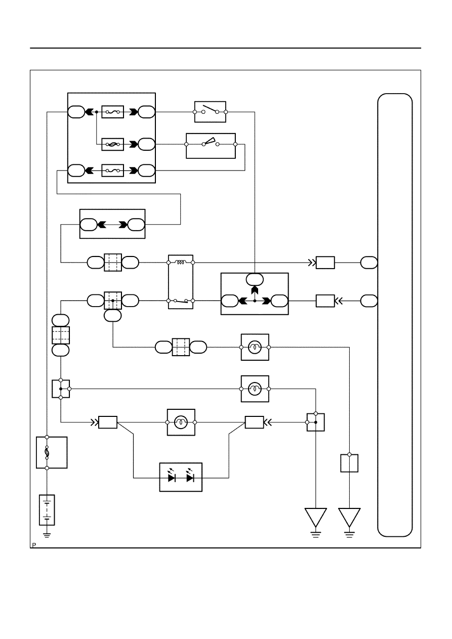
ABS & VSC Actuator
(Skid Control ECU)
G–Y
S14
Stop Light SW
I18 Ignition SW
1
4
W
W–L
IG1
AM1
2
1
B–Y
Instrument Panel J/B
2
1
1L
1F
1F
1C
1C
1
2
4
6
STOP
AM1
ECU–IG
W
4
B–R
Sub J/B No.3
3C
8
3A
8
B–R
B–R
J37
A
J/C
J38
A
B8 Brake
Inhibit Relay
B–R
L–O
L–O
IL1
7
L–O
S1
38
BSW
STP
S1
39
G–Y
IL2
13
1
2
3
4
G–Y
4B
1
1
1
4A
4C
J11
A
J10
C
J/C
C J10
G–Y
G–W
G–W
G–W
G–W
B
J33
J34
H
G–W
C
C
C
J44
C
J45
J
R8 Rear Combination Light RH
1
4
W–B
R7 Rear Combination Light LH
1
4
H9 High Mounted
Stop Light
A
A
A
J19
J/C
W–B
W–B
BD2
12
1
2
W–B
G–W
G–W
BD1
4
(*1)
(*1)
(*2)
(*2)
W–B
H9
High Mounted
Stop Light
1
2
J57
J/C
BP
BJ
F10
Fusible
Link
Block
ALT
8
5
B
Battery
*1: w/o Rear Spoiler
*2: w/ Rear Spoiler
J/C
G–W
J/C
G–W
Sub J/B No.4
Stop
Stop
DI–972
–
DIAGNOSTICS
ABS WITH EBD & BA & TRAC & VSC SYSTEM
1166
WIRING DIAGRAM
F13968
ON
1
3
–
DIAGNOSTICS
ABS WITH EBD & BA & TRAC & VSC SYSTEM
DI–973
1167
INSPECTION PROCEDURE
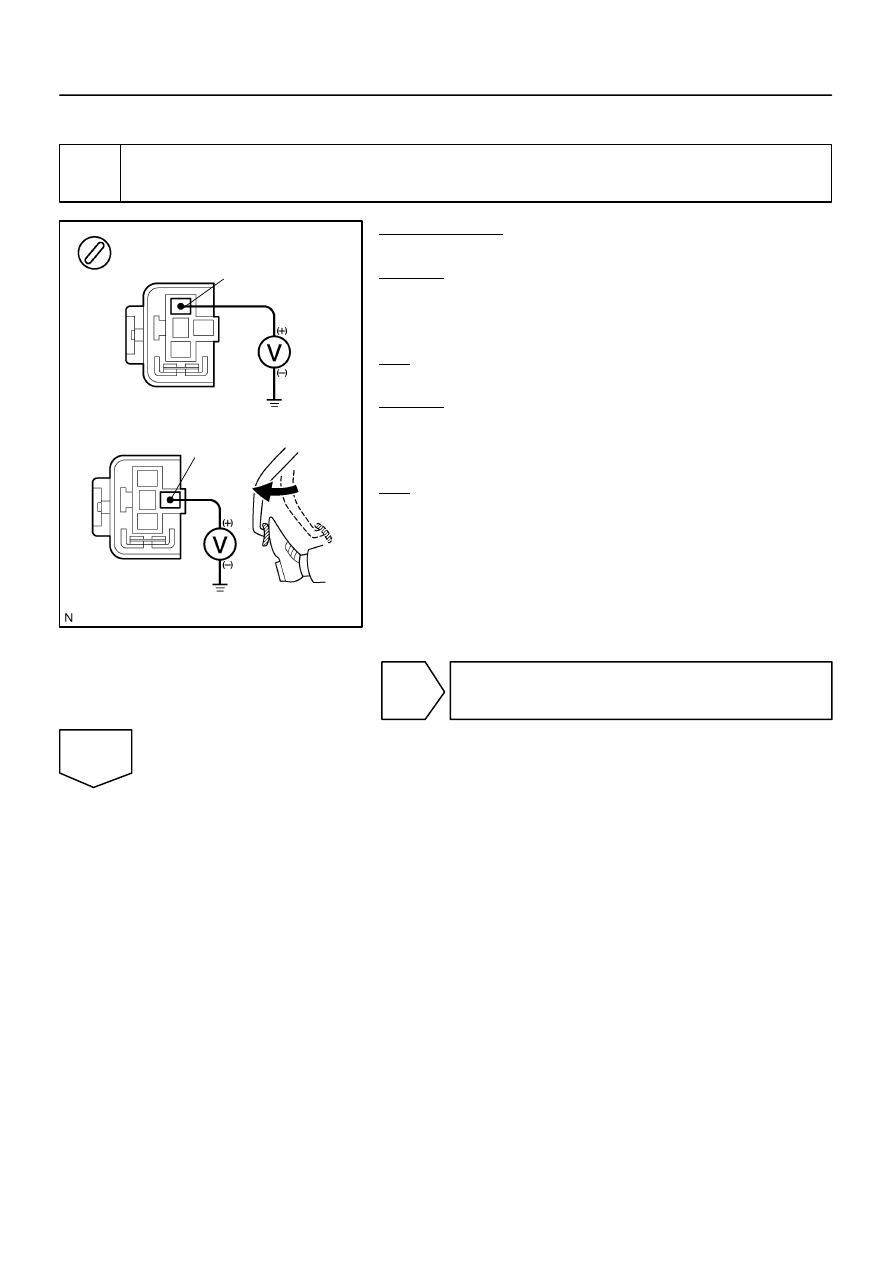
1
Check voltage between terminals 1 and 3 of the brake inhibit relay and body
ground.
PREPARATION:
Remove the brake inhibit relay from the connector.
CHECK:
(a)
Turn the ignition switch to the ON position.
(b)
Measure the voltage between terminal 1 of the brake in-
hibit relay harness side connector and body ground.
OK:
Voltage: 10 to 14 V
CHECK:
Measure the voltage between terminal 3 of the brake inhibit
relay harness side connector and body ground when the brake
pedal is depressed.
OK:
Voltage: 8 to 14 V
NG
Check and repair harness or connector.
OK
F17285
1
2
3
4
1
4
3
2
DI–974
–
DIAGNOSTICS
ABS WITH EBD & BA & TRAC & VSC SYSTEM
1168
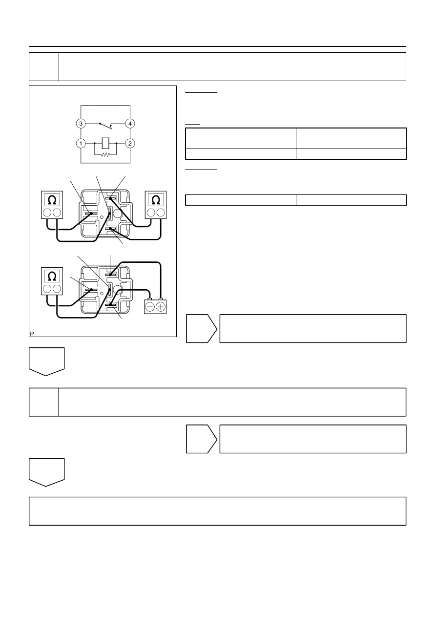
2
Check brake inhibit relay.
CHECK:
Check continuity between the following terminals of the brake
inhibit relay.
OK:
Terminals 1 and 2
Continuity
(Reference value 62
Ω
)
Terminals 3 and 4
Continuity
CHECK:
(a)
Apply battery positive voltage between terminals 1 and 2.
(b)
Check continuity between terminals.
Terminals 3 and 4
Open
NG
Replace brake inhibit relay.
OK
3
Check for open and short circuit in harness and connector between brake inhibit
relay and skid control ECU (See page
).
NG
Repair or replace harness or connector.
OK
If the same code is still indicated after the DTC is deleted, check the condition of each connection.
If the connections are normal, the skid control ECU may be defective.
NOTICE:
When replacing the skid control ECU, perform the zero point calibration (See page
).
Нет комментариевНе стесняйтесь поделиться с нами вашим ценным мнением.
Текст