Toyota Sequoia (2005). Manual — part 292

–
DIAGNOSTICS
ABS WITH EBD & BA & TRAC & VSC SYSTEM
DI–963
1157
DTC
C1249 / 49
Open Circuit in Stop Light Switch Cir-
cuit
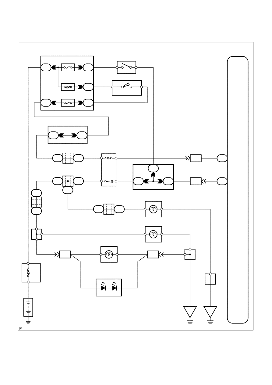
CIRCUIT DESCRIPTION
The skid control ECU inputs the stop light switch signal and detects the status of the brake operation.
The skid control ECU has an open detection circuit. If an open in the stop lamp switch input line or GND side
stop lamp circuit is detected when the stop lamp switch is off, this DTC is output.
DTC No.
DTC Detecting Condition
Trouble Area
C1249 / 49
ECU terminal STP voltage is low when both ignition switch
and stop light switch are ON.
Stop light switch
Stop light switch circuit
Skid control ECU
DI93P–03
F19773
ABS & VSC Actuator
(Skid Control ECU)
G–Y
S14
Stop Light SW
I18 Ignition SW
1
4
W
W–L
IG1
AM1
2
1
B–Y
Instrument Panel J/B
2
1
1L
1F
1F
1C
1C
1
2
4
6
STOP
AM1
ECU–IG
W
4
B–R
Sub J/B No.3
3C
8
3A
8
B–R
B–R
J37
A
J/C
J38
A
B8 Brake
Inhibit Relay
B–R
L–O
L–O
IL1
7
L–O
S1
38
BSW
STP
S1
39
G–Y
IL2
13
1
2
3
4
G–Y
4B
1
1
1
4A
4C
J11
A
J10
C
J/C
C J10
G–Y
G–W
G–W
G–W
G–W
B
J33
J34
H
G–W
C
C
C
J44
C
J45
J
R8 Rear Combination Light RH
1
4
W–B
R7 Rear Combination Light LH
1
4
H9 High Mounted
Stop Light
A
A
A
J19
J/C
W–B
W–B
BD2
12
1
2
W–B
G–W
G–W
BD1
4
(*1)
(*1)
(*2)
(*2)
W–B
H9
High Mounted
Stop Light
1
2
J57
J/C
BP
BJ
F10
Fusible
Link
Block
ALT
8
5
B
Battery
*1: w/o Rear Spoiler
*2: w/ Rear Spoiler
J/C
G–W
J/C
G–W
Sub J/B No.4
Stop
Stop
DI–964
–
DIAGNOSTICS
ABS WITH EBD & BA & TRAC & VSC SYSTEM
1158
WIRING DIAGRAM
F16994
STP
–
DIAGNOSTICS
ABS WITH EBD & BA & TRAC & VSC SYSTEM
DI–965
1159
INSPECTION PROCEDURE
1
Check operation of the stop light switch.
CHECK:
Check that the stop light comes on when the brake pedal is depressed and turns off when the brake pedal
is released.
OK:
Stop light switch operation is normal.
NG
Repair stop light circuit (See page
OK
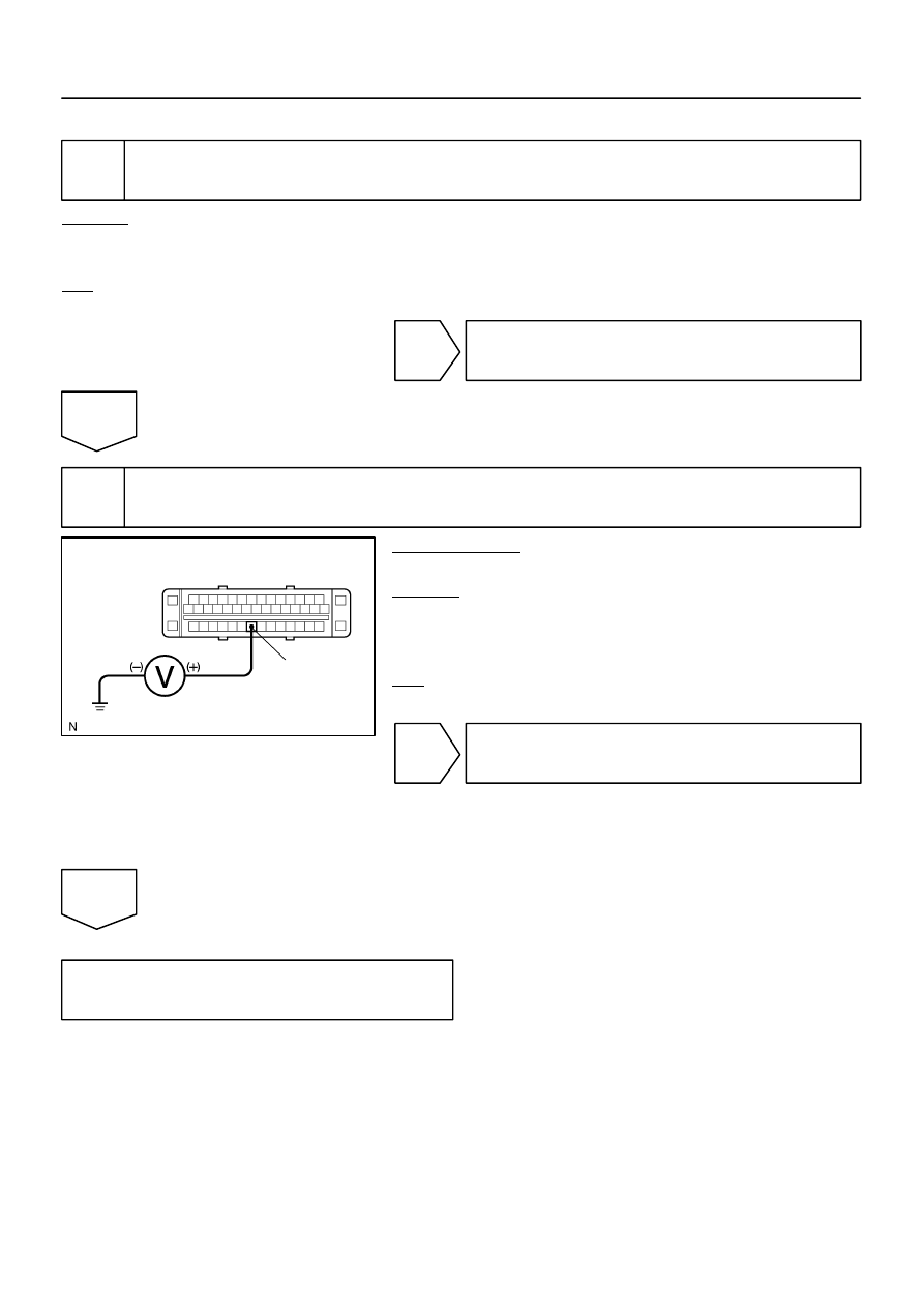
2
Check voltage between terminal STP of the skid control ECU and body ground.
PREPARATION:
Disconnect the skid control ECU connector.
CHECK:
Measure the voltage between terminal STP of the skid control
ECU harness side connector and body ground during depress-
ing the brake pedal.
OK:
Voltage: 8 to 14 V
OK
Replace skid control ECU
(See page
NOTICE:
When replacing the skid control ECU, perform the zero
point calibration (See page
NG
Check for open circuit in harness and con-
nector between skid control ECU and stop
light switch (See page
).
F19782
Battery
16
S1
+BS
GND1
GND2
+BM
S1
S1
S1
47
1
32
B–R
B–R
W–B
W–B
W–B
W–B
5
B
F10
Fusible Link Block
ABS & VSC Actuator
(Skid Control ECU)
IG
J18
J/C
A
A
3
ABS
Motor Relay
Pump
Motor
IL1
17
IL1
9
DI–966
–
DIAGNOSTICS
ABS WITH EBD & BA & TRAC & VSC SYSTEM
1160
DTC
C1251 / 51
Pump Motor is Locked/
Open Circuit in Pump Motor Circuit
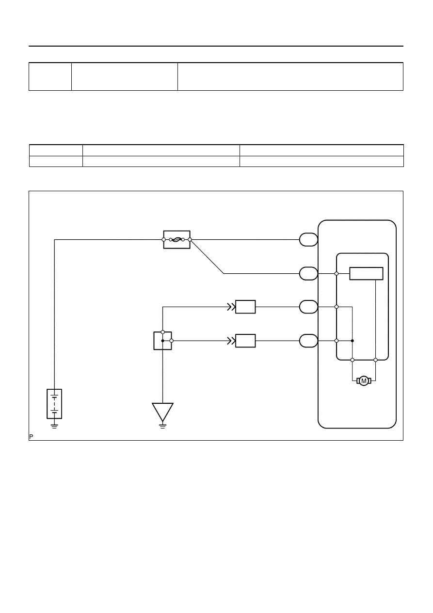
CIRCUIT DESCRIPTION
ABS pump motor is located inside the brake actuator.
The motor is used for BA, TRAC and VSC operation.
DTC No.
DTC Detecting Condition
Trouble Area
C1251 / 51
Pump motor does not operate during the initial check.
ABS & VSC actuator
WIRING DIAGRAM
DIDMC–01
Нет комментариевНе стесняйтесь поделиться с нами вашим ценным мнением.
Текст