Toyota Sequoia (2005). Manual — part 295
–
DIAGNOSTICS
ABS WITH EBD & BA & TRAC & VSC SYSTEM
DI–975
1169
DTC
C1337 / 37
Some Tire Are Different in Size From
the Other Tires
CIRCUIT DESCRIPTION
Skid control ECU measure the speed of each wheel by receiving signals from speed sensor. These signals
are used for recognizing all 4 wheels are operating properly. Therefore, all wheel signals must be equal.
DTC No.
DTC Detecting Condition
Trouble Area
C1337 / 37
1 or 2 tires of different size are used for driving.
Tire size
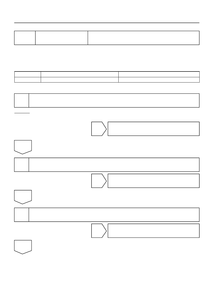
INSPECTION PROCEDURE
1
Check tire size.
CHECK:
Check tire size and condition of all 4 wheels.
NG
Replace tires so that all 4 tires are the same in
size.
OK
2
NG
Replace speed sensor.
OK
3
Check speed sensor rotor (See page
).
NG
Replace speed sensor rotor.
OK
DI93T–03

DI–976
–
DIAGNOSTICS
ABS WITH EBD & BA & TRAC & VSC SYSTEM
1170
4
Check harness and connector between speed sensor and skid control ECU
(See page
).
NG
Repair or replace harness or connector.
OK
Replace skid control ECU
(See page
).
NOTICE:
When replacing the skid control ECU, perform the zero point calibration (See page
).

–
DIAGNOSTICS
ABS WITH EBD & BA & TRAC & VSC SYSTEM
DI–977
1171
DTC
C1340 / 47
Center DIFF. Lock Circuit Malfunction
CIRCUIT DESCRIPTION
This circuit sends the signal to the ECU by detecting that the transfer center differential is in the ”LOCK” posi-
tion.
DTC No.
DTC Detecting Condition
Trouble Area
C1340 / 47
Center diff. lock position switch signal does not change
Center diff. lock position switch
Center diff. lock position switch circuit
Center diff. lock Indicator light circuit
Translate ECU
DIDMD–01
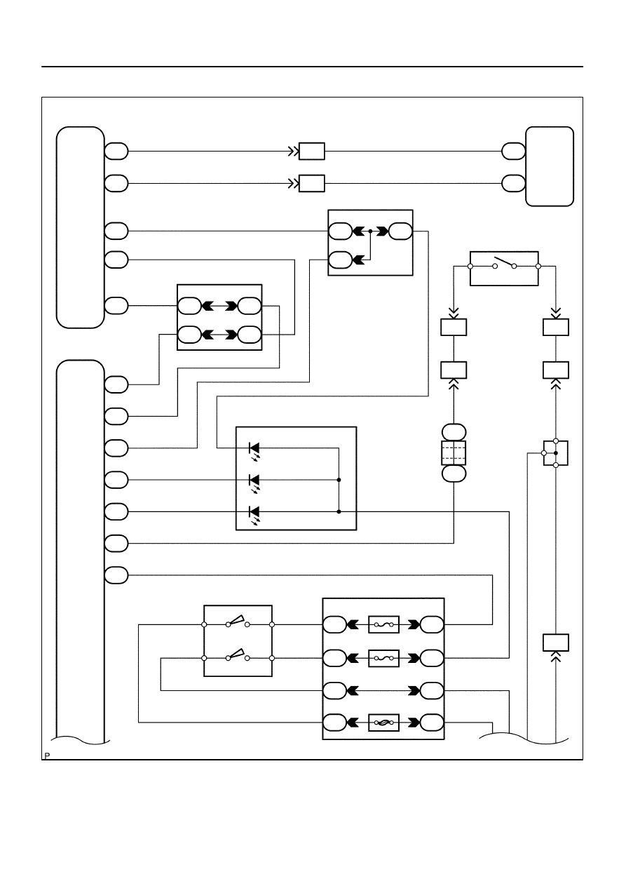
F19774
Translate Shift Actuator
ABS & VSC Actuator
(Skid Control ECU)
VSC–
CD
EXI2
CSW
VSC+
7
T5
11
T5
29
T5
31
T5
26
T5
L
L
W
BR–Y (4WD)
W
7
IL2
6
IL2
6
S1
2
S1
CANH
CANL
Sub J/B No.3
Y–G (4WD)
BR–Y
9
3C
9
3A
9
3B
A10
ADD Actuator
ADD
GND
BR–Y
Sub J/B No.4
8
4B
7
4A
7
4B
8
4A
L–W
L–W
(4WD)
4WD
Control ECU
4
F23
16
F23
20
F23
11
F23
19
F23
3
F23
6
F23
DL
IND2
IG
ADD
P1
IND3
IND1
Y–B
L–W
BR–Y
L–W
BR–Y
BR–Y
BR–Y
G–W
Y–B
GR
B–Y
C6
Combination Meter
Center Diff. Lock
4LO
4HI
24
B–O
GR
GR
GR
GR
W–B
W–B
W–B
W–B
W–B
W–B
1
3
D
B
EC1
EB5
J51
J52
6
4
EC1
EB5
A
A
A J41
J/C
IG4
21
B–Y
Instrument Panel J/B
I18
Ignition SW
B–O
W–R
W
B–Y
B–R
W–R
W–L
W–L
W–R
4WD
IGN1
AM1
AM1
IG1
AM2
IG2
2
6
4
1C
2
1C
3
1C
6
1C
8
1D
11
1H
7
1J
1
1L
1
2
3
4
J/C
1
2
1
5
4
5
6
3
4
DI–978
–
DIAGNOSTICS
ABS WITH EBD & BA & TRAC & VSC SYSTEM
1172
WIRING DIAGRAM
Нет комментариевНе стесняйтесь поделиться с нами вашим ценным мнением.
Текст