Toyota Sequoia (2005). Manual — part 318
DIDI3–01
DTC
Trouble Mode
Output from
Output DTC
ECM
Communication
Stop Mode
Translate ECU
Communication
Stop Mode
Suspension Control
ECU Communication
Stop Mode (*1)
Skid Control
ECU
Translate ECU
Suspension
Control
ECU (*1)
See page
U0100/65
65
94
U0100/65
U0122/67
U0132/71
–
–
–
–
–
–
–
DIAGNOSTICS
CAN COMMUNICATION SYSTEM
DI–1067
1261
PROBLEM SYMPTOMS TABLE
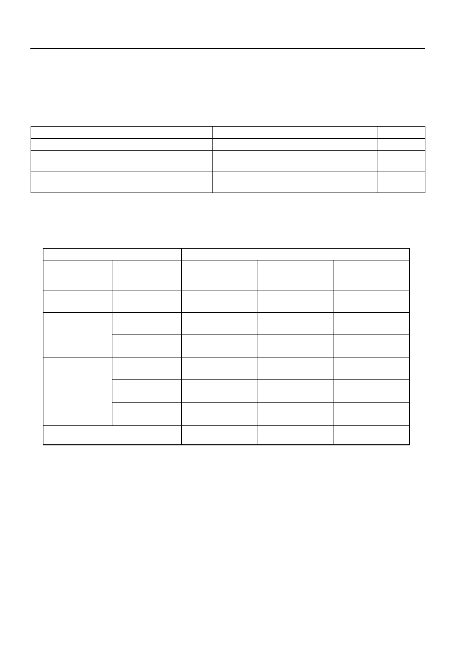
1.
COMMUNICATION STOP MODE TABLE
(a)
Complete ”Check CAN Bus Line” (see page
) to confirm that there is no malfunction in the CAN
bus line. Select ”BUS CHECK” on the hand–held tester via the CAN VIM (see page
).
(b)
Check the communication stop mode of the ECUs not displayed among the following: ”ENGINE”,
”TRANSLATE ECU”, or ”REAR AIRSUS”.
Symptom
Inspection Item
See page
”ENGINE” is not displayed on the hand–held tester via CAN VIM.
ECM Communication Stop Mode
”TRANSLATE ECU” is not displayed on the hand–held tester via
CAN VIM.
Translate ECU Communication Stop Mode
”REAR AIRSUS” is not displayed on the hand–held tester via
CAN VIM. (*1)
Suspension Control ECU Communication Stop Mode
HINT:
*1: w/ Air Suspension System
2.
DTC COMBINATION TABLE
(a)
Perform troubleshooting according to the combination of DTCs output.
HINT:
*1: w/ Air Suspension System
: DTCs that are being output.
–: DTCs that are not being output.
Previous CAN communication system DTCs may be the cause if CAN communication system DTCs
are output and all ECUs connected to the CAN communication system are displayed on the hand–held
tester’s ”BUS CHECK” screen via the CAN VIM.
DIDI4–01
F19816
Junction Connector ”B” Side
(w/o Earth Terminal):
Junction Connector ”A” Side
(w/ Earth Terminal):
Earth Terminal
Junction
Connector
J53
J54
J55
G
W
L
W
B
W
R
W
J56 (*1)
DI–1068
–
DIAGNOSTICS
CAN COMMUNICATION SYSTEM
1262
TERMINALS OF ECU
HINT:
This section describes the standard CAN values for all CAN re-
lated components.
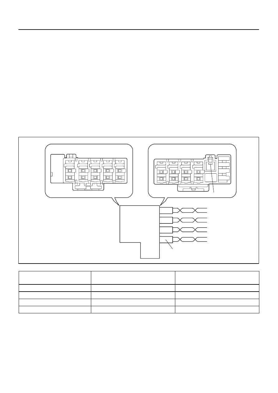
1.
Junction Connector
HINT:
The connectors connected to the junction connector can
be distinguished by the colors of the bus lines and the
connecting side of the connector.
J53, J54, J55 and J56 are interchangeable.
*1: w/ Air Suspension System
CAN J/C connectors
(A side, w/ earth terminal)
Color (CAN–H Side)
Color (CAN–L Side)
ECM (J53)
L
W
DLC3 (J54)
B
W
Translate ECU (J55)
R
W
Suspension Control ECU (J56) *1
G
W
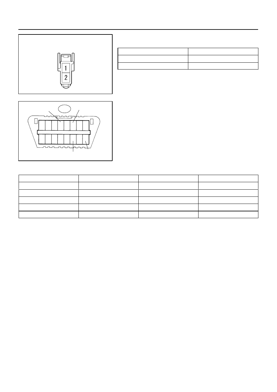
F19735
CAN J/C Connector Front View:
1
2
3
4
5
6
7
8
9 10 11 12 13 14 15 16
F19737
DLC3:
D6
CANH
CG
BAT
CANL
–
DIAGNOSTICS
CAN COMMUNICATION SYSTEM
DI–1069
1263
2.
The Terminals of Connectors for the Junction Con-
nector
Terminal
Terminal symbol
1
CANH
2
CANL
3.
DLC3
(a)
Measure the resistance according to the value(s) in the
table below.
Standard:
Terminals
Wiring Color
Condition
Specified Value
D6–6 (CANH) – D6–14 (CANL)
B – W
Ignition Switch OFF
54 to 69
Ω
D6–6 (CANH) – D6–4 (CG)
B – O
Ignition Switch OFF
3 k
Ω
or more
D6–14 (CANL) – D6–4 (CG)
W – O
Ignition Switch OFF
3 k
Ω
or more
D6–6 (CANH) – D6–16 (BAT)
B – W–R
Ignition Switch OFF
1 M
Ω
or more
D6–14 (CANL) – D6–16 (BAT)
W – W–R
Ignition Switch OFF
1 M
Ω
or more
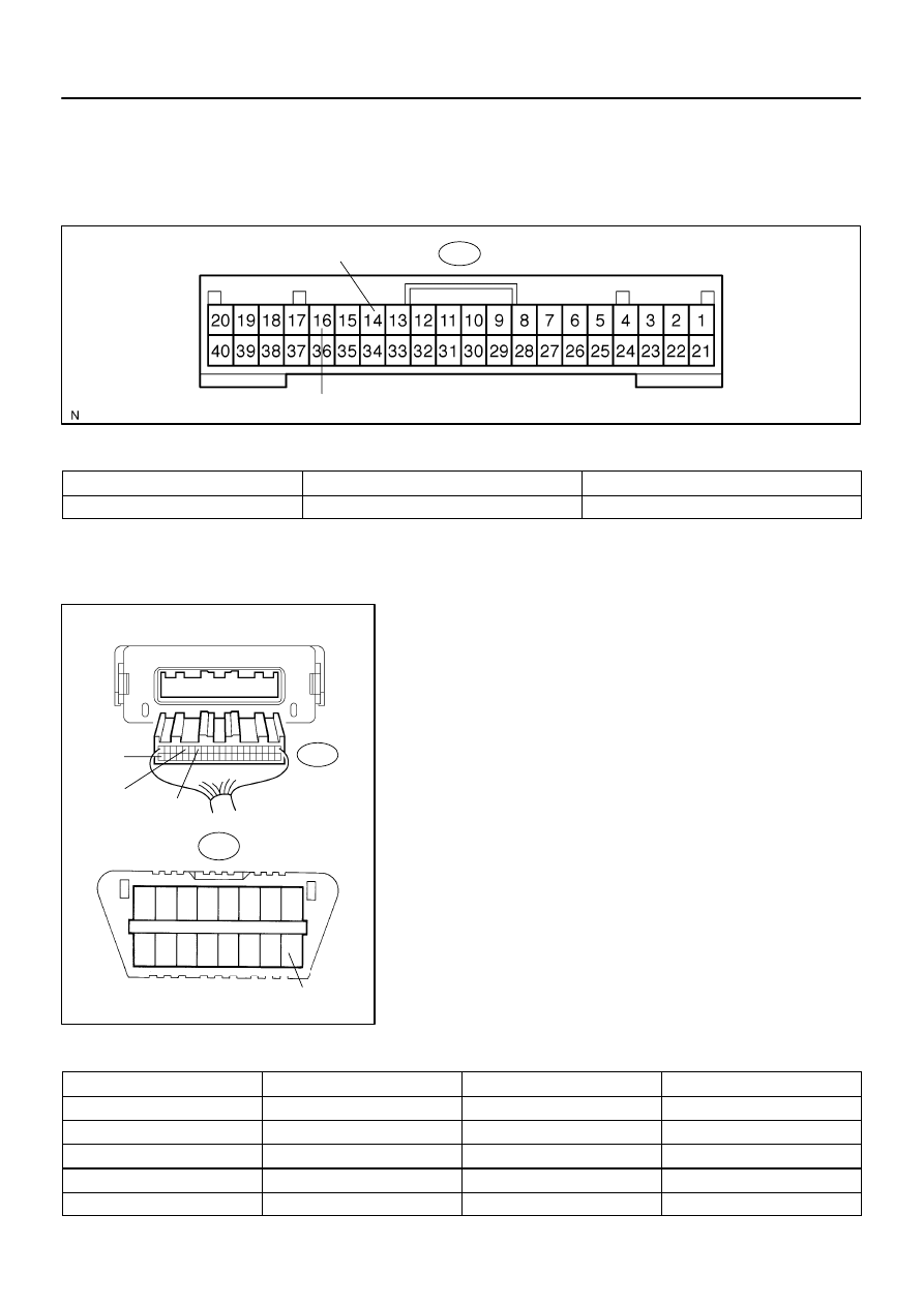
F16975
Translate ECU:
T5
ENG+
ENG–
1
2
3
4
5
6
7
8
9 10 11 12 13 14 15 16
F19737
F19152
F19830
Translate ECU Wire Harness View:
T5
GND
ENG–
ENG+
DLC3:
D6
BAT
DI–1070
–
DIAGNOSTICS
CAN COMMUNICATION SYSTEM
1264
4.
Translate ECU
(a)
Measure the resistance according to the value(s) in the
table below.
Standard:
Terminals
Condition
Specified Value
T5–14 (ENG+) – T5–16 (ENG–)
Ignition Switch OFF
108 to 132
Ω
(b)
Measure the resistance according to the value(s) in the
table below.
Standard:
Terminals
Wiring Color
Condition
Specified Value
T5–14 (ENG+) – T5–16 (ENG–)
R – W
Ignition Switch OFF
108 to 132
Ω
T5–14 (ENG+) – T5–40 (GND)
R – O
Ignition Switch OFF
3 k
Ω
or more
T5–16 (ENG–) – T5–40 (GND)
W – O
Ignition Switch OFF
3 k
Ω
or more
T5–14 (ENG+) – D6–16 (BAT)
R – W–R
Ignition Switch OFF
1 M
Ω
or more
T5–16 (ENG–) – D6–16 (BAT)
W – W–R
Ignition Switch OFF
1 M
Ω
or more
Нет комментариевНе стесняйтесь поделиться с нами вашим ценным мнением.
Текст