Toyota Sequoia (2005). Manual — part 319
B17410
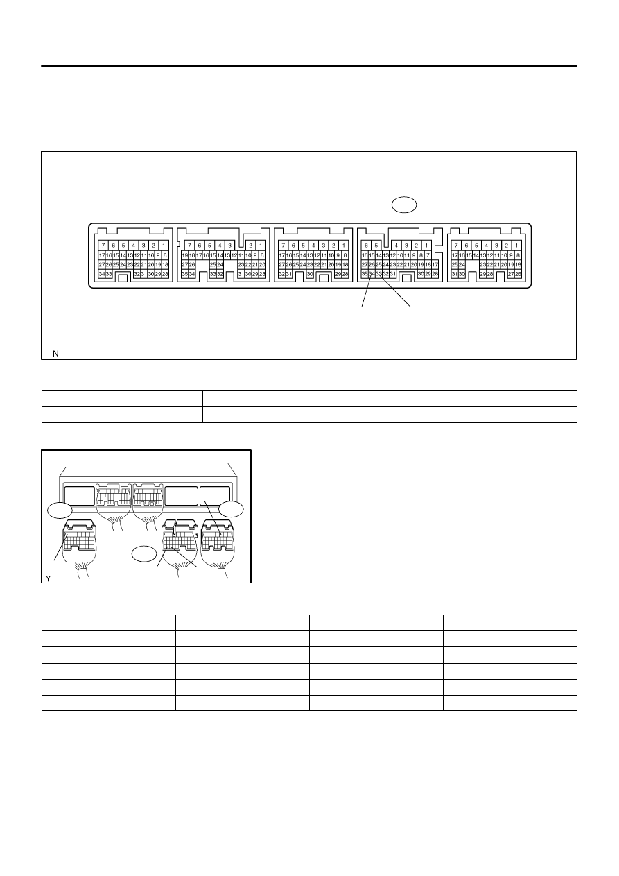
ECM:
CANL
CANH
E5
F19578
ECM Wire Harness View:
E4
E5
E8
BATT
E0I
CANL
CANH
–
DIAGNOSTICS
CAN COMMUNICATION SYSTEM
DI–1071
1265
5.
ECM
(a)
Measure the resistance according to the value(s) in the
table below.
Standard:
Terminals
Condition
Specified Value
E5–33 (CANH) – E5–34 (CANL)
Ignition Switch OFF
108 to 132
Ω
(b)
Measure the resistance according to the value(s) in the
table below.
Standard:
Terminals
Wiring Color
Condition
Specified Value
E5–33 (CANH) – E5–34 (CANL)
L – W
Ignition Switch OFF
108 to 132
Ω
E5–33 (CANH) – E8–7 (E0I)
L – W–B
Ignition Switch OFF
3 k
Ω
or more
E5–34 (CANL) – E8–7 (E0I)
W – W–B
Ignition Switch OFF
3 k
Ω
or more
E5–33 (CANH) – E4–3 (BATT)
L – B–Y
Ignition Switch OFF
1 M
Ω
or more
E5–34 (CANL) – E4–3 (BATT)
W – B–Y
Ignition Switch OFF
1 M
Ω
or more
F16805
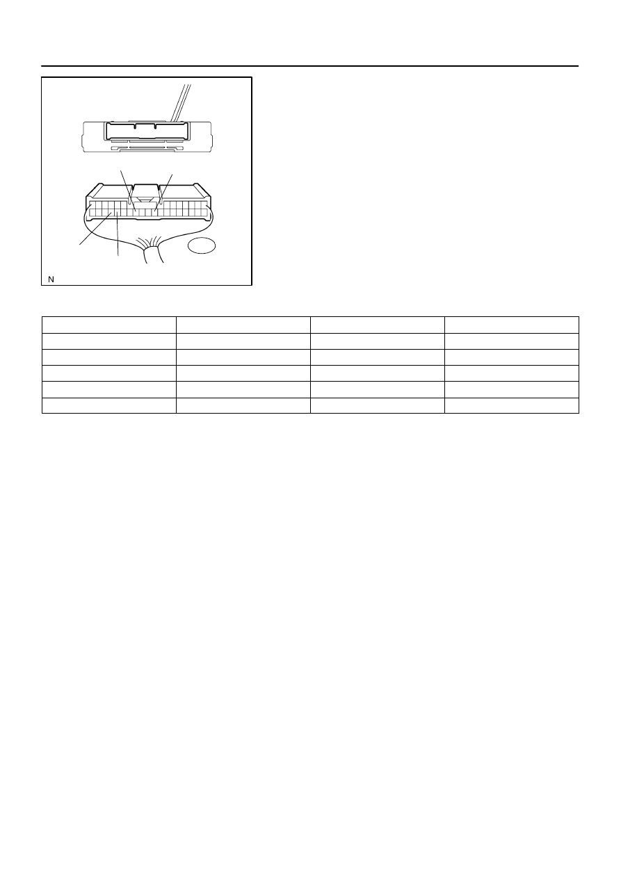
Suspension Control ECU
Wire Harness View:
S25
GND
BAT
CANH
CANL
DI–1072
–
DIAGNOSTICS
CAN COMMUNICATION SYSTEM
1266
6.
Suspension Control ECU
(a)
Measure the resistance according to the value(s) in the
table below.
Standard:
Terminals
Wiring Color
Condition
Specified Value
S25–29 (CANH) – S25–28 (CANL)
G – W
Ignition Switch OFF
54 to 69
Ω
S25–29 (CANH) – S25–22 (GND)
G – W–B
Ignition Switch OFF
3 k
Ω
or more
S25–28 (CANL) – S25–22 (GND)
W – W–B
Ignition Switch OFF
3 k
Ω
or more
S25–29 (CANH) – S25–25 (BAT)
G – V
Ignition Switch OFF
1 M
Ω
or more
S25–28 (CANL) – S25–25 (BAT)
W – V
Ignition Switch OFF
1 M
Ω
or more
DIDI5–01
F19740
F19741
F19742
–
DIAGNOSTICS
CAN COMMUNICATION SYSTEM
DI–1073
1267
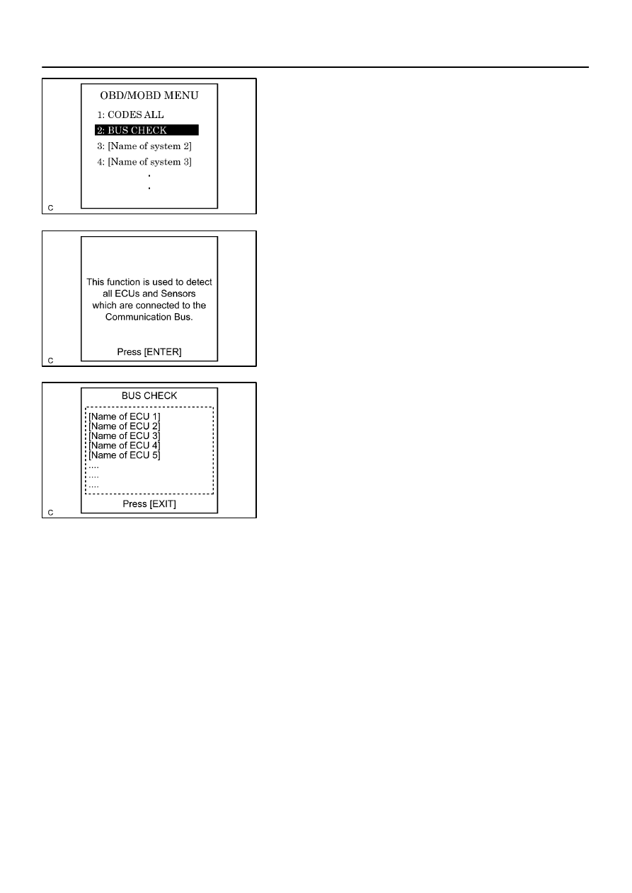
DIAGNOSIS SYSTEM
1.
BUS CHECK
HINT:
The ECUs that are properly connected to the CAN communica-
tion system can be displayed using the hand–held tester via
CAN VIM.
(a)
Select ”BUS CHECK” from the ”OBD/MOBD MENU”
screen.
(b)
Press ”ENTER” on the hand–held tester via CAN VIM.
(c)
The screen displays the ECUs and sensors that are prop-
erly connected to the CAN communication system.
HINT:
There is a communication stop in the system of any properly
connected ECUs or sensors that are not displayed
(see page
).
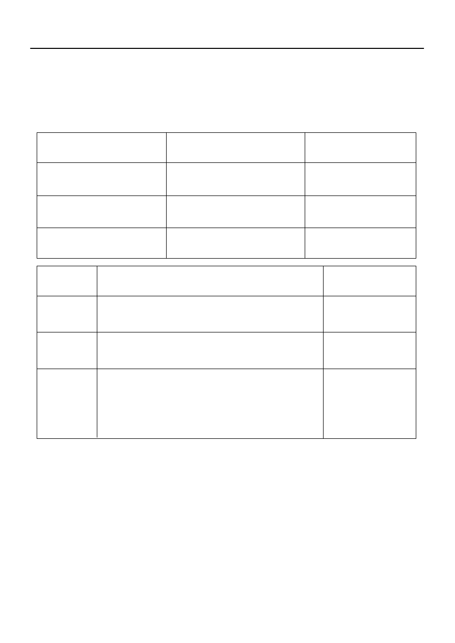
DIDI6–01
Action when unable to communicate
DTC detection
(Driver detectable)
Suspension
Control ECU
VSC/TRC function stops
[When unable to communicate with ECM]
Function stops (Vehicle height cannot be changed until the ignition
switch is turned off)
[When unable to communicate with Translate ECU]
Vehicle height is maintained at the normal level until the ignition
switch is turned off. If communication is still impossible even after
the ignition switch is turned on again, the same height is maintained.
Not detectable
(
)
Not detectable
(VSC warning lamp
comes on)
Detectable
(Only DTCs are stored)
ECM
Translate ECU
Suspension Control ECU
Rx
Tx
Tx
Rx
Tx
Tx
Tx
Rx
ECM
Translate ECU
DI–1074
–
DIAGNOSTICS
CAN COMMUNICATION SYSTEM
1268
FAIL–SAFE CHART
1.
FAIL–SAFE FUNCTION
(a)
When communication fails in any of the CAN bus lines (communication lines) due to a short circuit or
any other cause, the fail–safe function, which is specified for each system, operates to prevent the
system from malfunctioning.
(b)
Effects on each system when communication is impossible are as follows.
HINT:
Rx: Reception from each ECU.
Tx: Transmission to each ECU.
Нет комментариевНе стесняйтесь поделиться с нами вашим ценным мнением.
Текст