Toyota Sequoia (2005). Manual — part 637
I28836
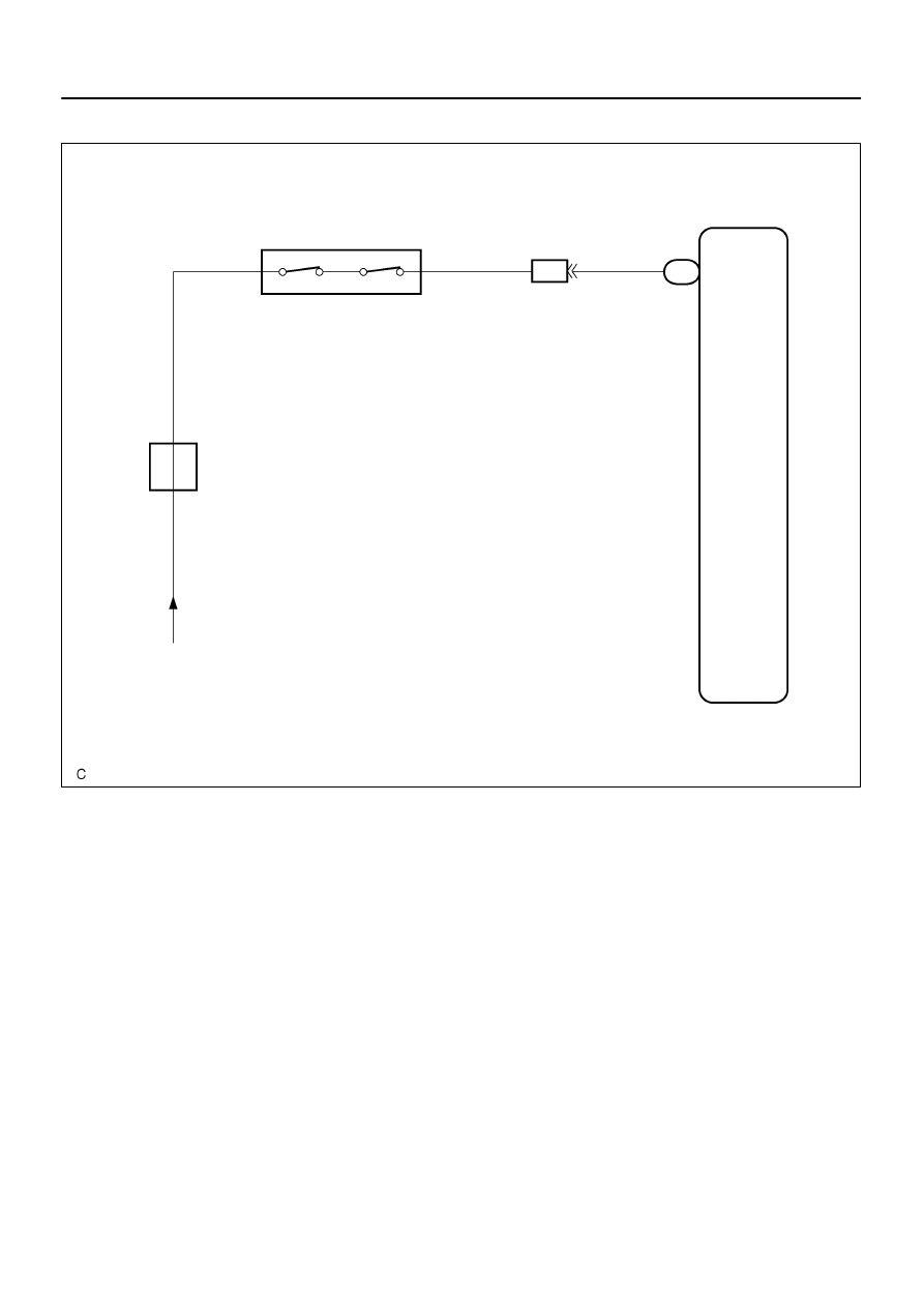
Integration Control
and Panel
PSW
L–B
R–Y
R–Y
4
A4
A/C Pressure Switch
I19
C
4
6
IA5
1
J3
J/C
From
HTR Fuse
L–B
C
Dual
–
DIAGNOSTICS
AIR CONDITIONING SYSTEM
DI–2343
2537
WIRING DIAGRAM
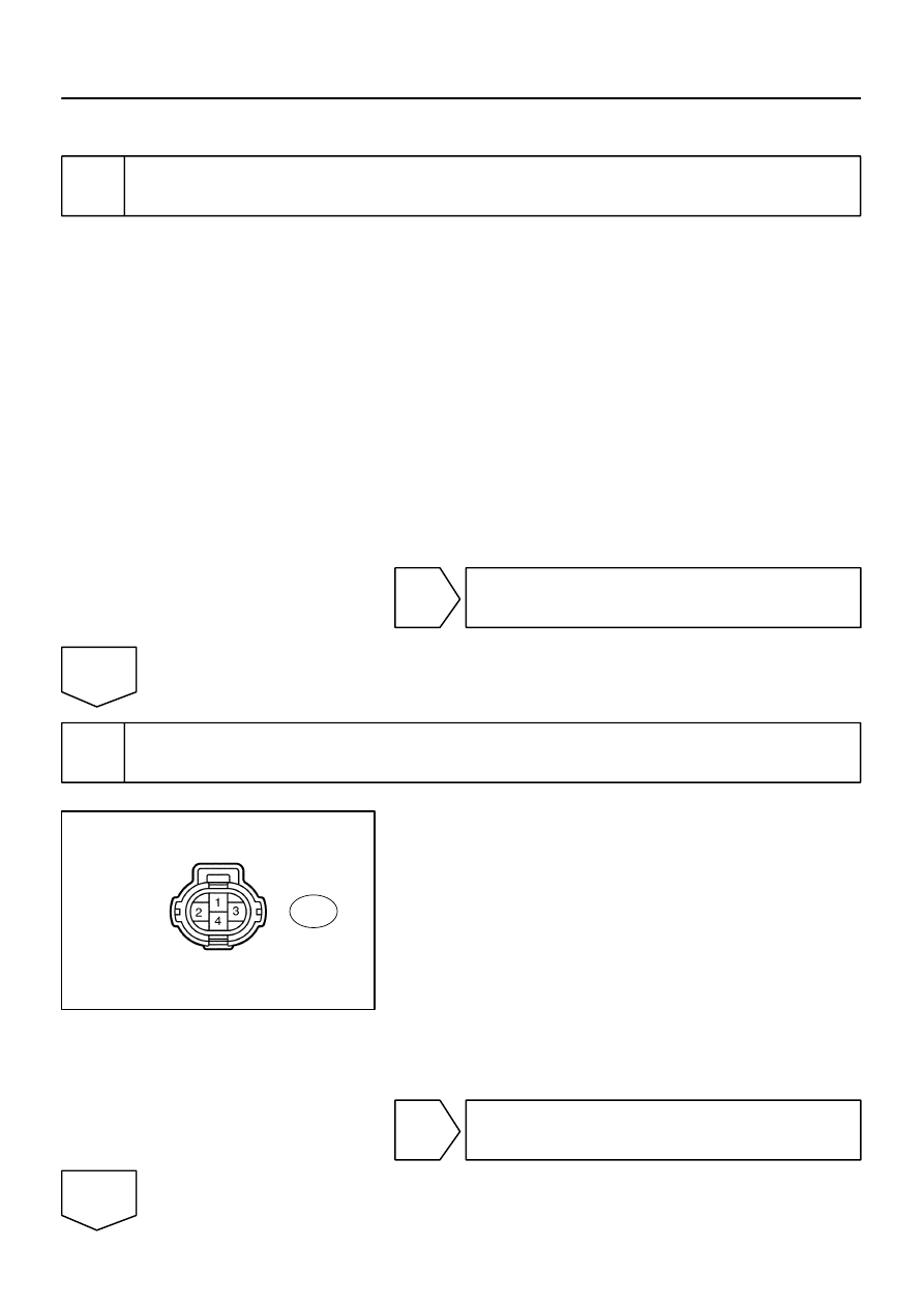
I29010
Pressure switch:
A4
DI–2344
–
DIAGNOSTICS
AIR CONDITIONING SYSTEM
2538
INSPECTION PROCEDURE
1
Check refrigerant pressure.
(a)
Set the manifold gauge.
(b)
Read the manifold gauge pressure when these conditions are established.
Test conditions:
Temperature at the air inlet with the switch set at RECIRC is 30 to 35
°
C (86 to 95
°
F)
Engine running at 1,500 rpm
Blower speed control switch at ”HI” position
Temperature control dial at ”COOL” position
Air conditioning switch ON
Fully open doors
Standard:
Pressure on high pressure side:
1.37 to 1.57 MPa (13.9 to 16.0 kgf
⋅
cm
2
, 198 to 228 psi)
HINT:
If the refrigerant pressure is below 196 KPa (2.0 kgf
⋅
cm
2
, 28 psi), the refrigerant amount the air conditioning
cycle may have decreased significantly for reasons such as a gas leakage.
NG
Check air conditioning cycle
(See page
OK
2
Check air conditioning operation.
(a)
Disconnect the pressure switch connector.
(b)
Connect terminals 1 and 4 of the connector of the pres-
sure switch on the vehicle wire harness side using a ser-
vice wire.
(c)
Start the engine.
(d)
Turn the air conditioning switch is on and check that the
magnet clutch is turned on.
(e)
Check that the magnet clutch is turned off when discon-
necting terminals 1 and 4 (that are connected in the prior
step).
OK:
Terminals 1 and 4 connected: magnet clutch is on
Terminals 1 and 4 disconnected: magnet clutch is off
NG
Go to step 3.
OK

–
DIAGNOSTICS
AIR CONDITIONING SYSTEM
DI–2345
2539
Replace pressure switch.
3
Check harness and connector between pressure switch and integration control
and panel (See page
).
Result:
NG
A
OK (Checking from the PROBLEM SYMPTOMS TABLE)
B
OK (Checking from the DTC)
C
A
Repair or replace harness or connector.
B
Proceed to next circuit inspection shown in
problem symptoms table (See page
OK
Replace integration control and panel.
4
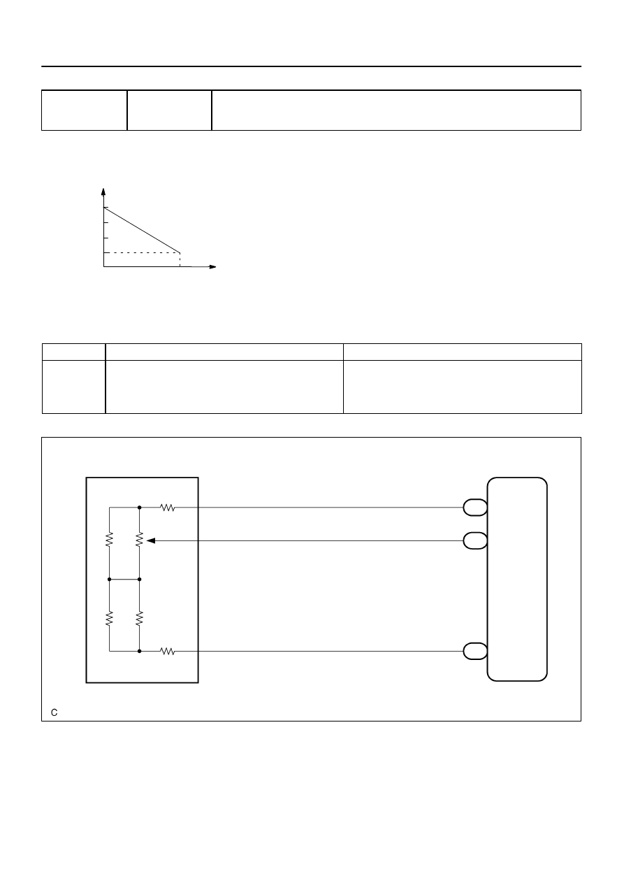
(V)
1
TP terminal
voltage
0
100 %
(Cool)
(Hot)
Damper opening angle
I28837
A17
Air Mix Control
Servomotor (Front)
5
L–R
4
3
22
15
12
S5–AM
TP
SG–TP
Integration Control
and Panel
I20
R–Y
G–R
VZ
PT
GND
I20
I20
DI–2346
–
DIAGNOSTICS
AIR CONDITIONING SYSTEM
2540
DTC
31
Front Air Mix Damper Position Sensor Cir-
cuit
CIRCUIT DESCRIPTION
This sensor detects the position of the air mix damper and
sends the appropriate signals to the integration control and
panel.
The position sensor is built into the air mix damper control ser-
vomotor assembly.
DTC No.
Detection Item
Trouble Area
31
Short to ground or short to power source circuit in front air mix
Front air mix damper position sensor
Harness or connector between front air mix damper position
31
Short to ground or short to ower source circuit in front air mix
damper position sensor circuit.
Harness or connector between front air mix dam er osition
sensor and integration control and panel
Integration control and panel
WIRING DIAGRAM
DI3FF–10
Нет комментариевНе стесняйтесь поделиться с нами вашим ценным мнением.
Текст