Toyota Sequoia (2005). Manual — part 635
I08309
2
1
I28970
Resistance (k
Ω
)
Temperature
4.0
2.0
3.5
1.5
0.0
10
3.0
1.0
2.5
0.5
20
30
40
50
60
68
86
104
122
140
(
C)
(
F)
50
–
DIAGNOSTICS
AIR CONDITIONING SYSTEM
DI–2335
2529
2
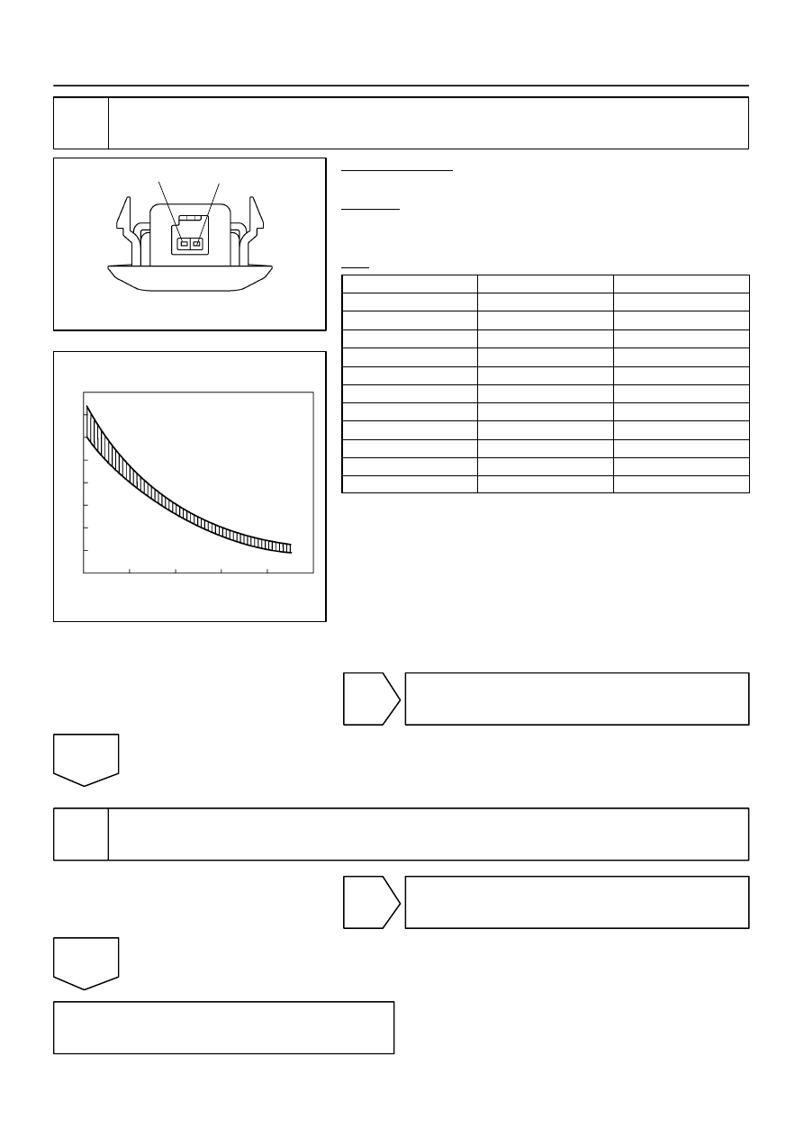
Check rear room temperature sensor.
PREPARATION:
Disconnect the rear room temperature sensor connector.
CHECK:
Measure the resistance between terminals 1 and 2 of the room
temperature sensor connector at each temperature.
OK:
Tester connection
Condition
Specified condition
1–2
10
C (50
F)
3.00 to 3.73 k
Ω
1–2
15
C (59
F)
2.45 to 2.88 k
Ω
1–2
20
C (68
F)
1.95 to 2.30 k
Ω
1–2
25
C (77
F)
1.60 to 1.80 k
Ω
1–2
30
C (86
F)
1.28 to 1.47 k
Ω
1–2
35
C (95
F)
1.00 to 1.22 k
Ω
1–2
40
C (104
F)
0.80 to 1.00 k
Ω
1–2
45
C (113
F)
0.65 to 0.85 k
Ω
1–2
50
C (122
F)
0.50 to 0.70 k
Ω
1–2
55
C (131
F)
0.44 to 0.60 k
Ω
1–2
60
C (140
F)
0.36 to 0.50 k
Ω
NOTICE:
Even slightly touching the sensor may change the re-
sistance value. Be sure to hold the connector of the
sensor.
When measuring, the sensor temperature must be
the same as the ambient temperature.
HINT:
As the temperature increases, the resistance decreases (see
the graph on the left).
NG
Replace rear room temperature sensor.
OK
3
Check harness and connector between rear room temperature sensor and in-
tegration control and panel (See page
NG
Repair or replace harness or connector.
OK
Replace integration control and panel.
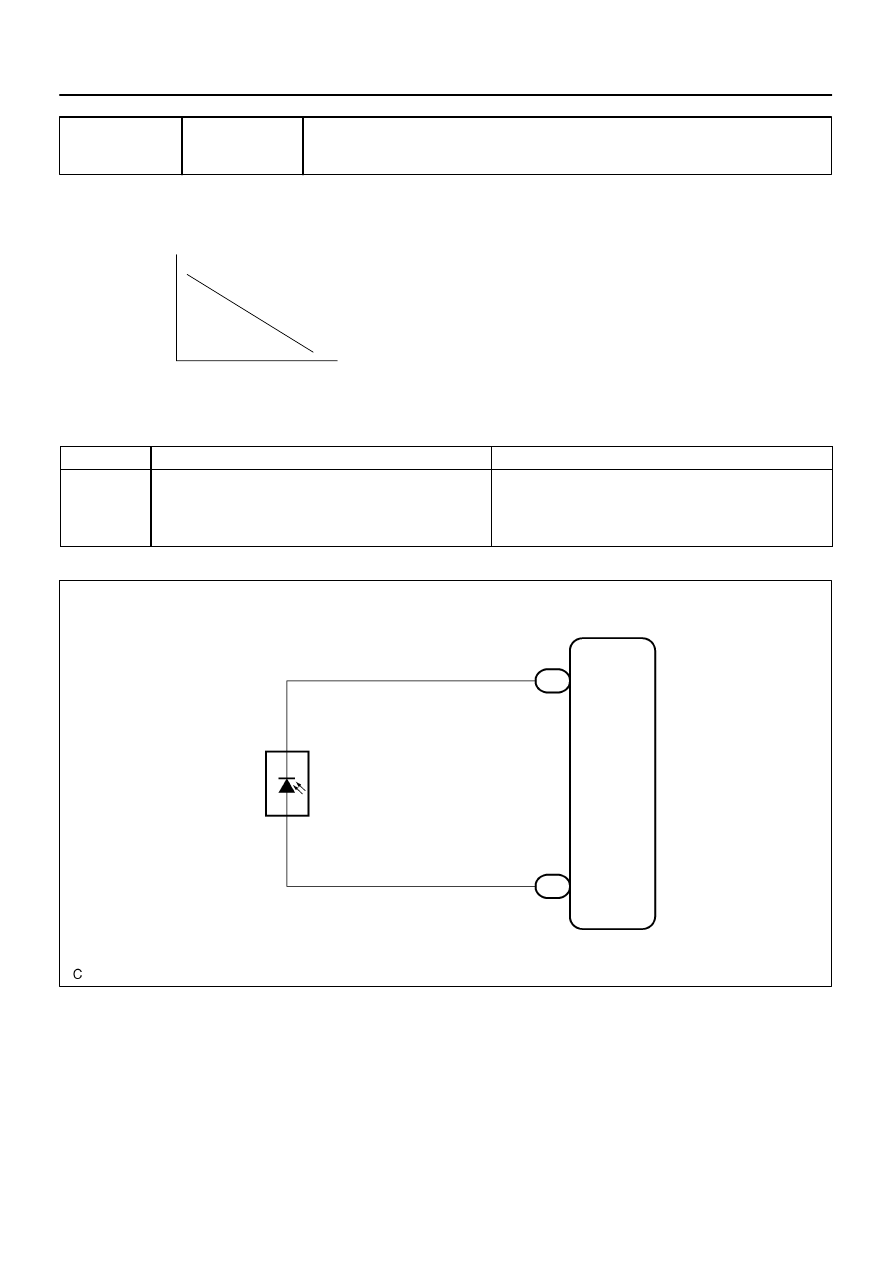
Resistance of photo diode
High
Low
Weak
Strong
Strength of solar radiation
I28834
A15
Solar
Sensor
TS
21
Integration Control and Panel
14
S5–TS
I20
B
LG
1
2
I20
DI–2336
–
DIAGNOSTICS
AIR CONDITIONING SYSTEM
2530
DTC
21
Solar Sensor Circuit
CIRCUIT DESCRIPTION
A photo diode in the solar sensor detects solar radiation and
sends signals to the integration control and panel.
DTC No
Detection Item
Trouble Area
21
Open or short in solar sensor circuit.
Note that output of diagnostic trouble code 21 is not abnormal
when the sensor is not receiving solar radiation.
Solar sensor
Harness or connector between solar sensor and integration
control and panel
Integration control and panel
WIRING DIAGRAM
DI3FB–11
I28847
TS
S5–TR
I20
Integration Control and Panel:
–
DIAGNOSTICS
AIR CONDITIONING SYSTEM
DI–2337
2531
INSPECTION PROCEDURE
1
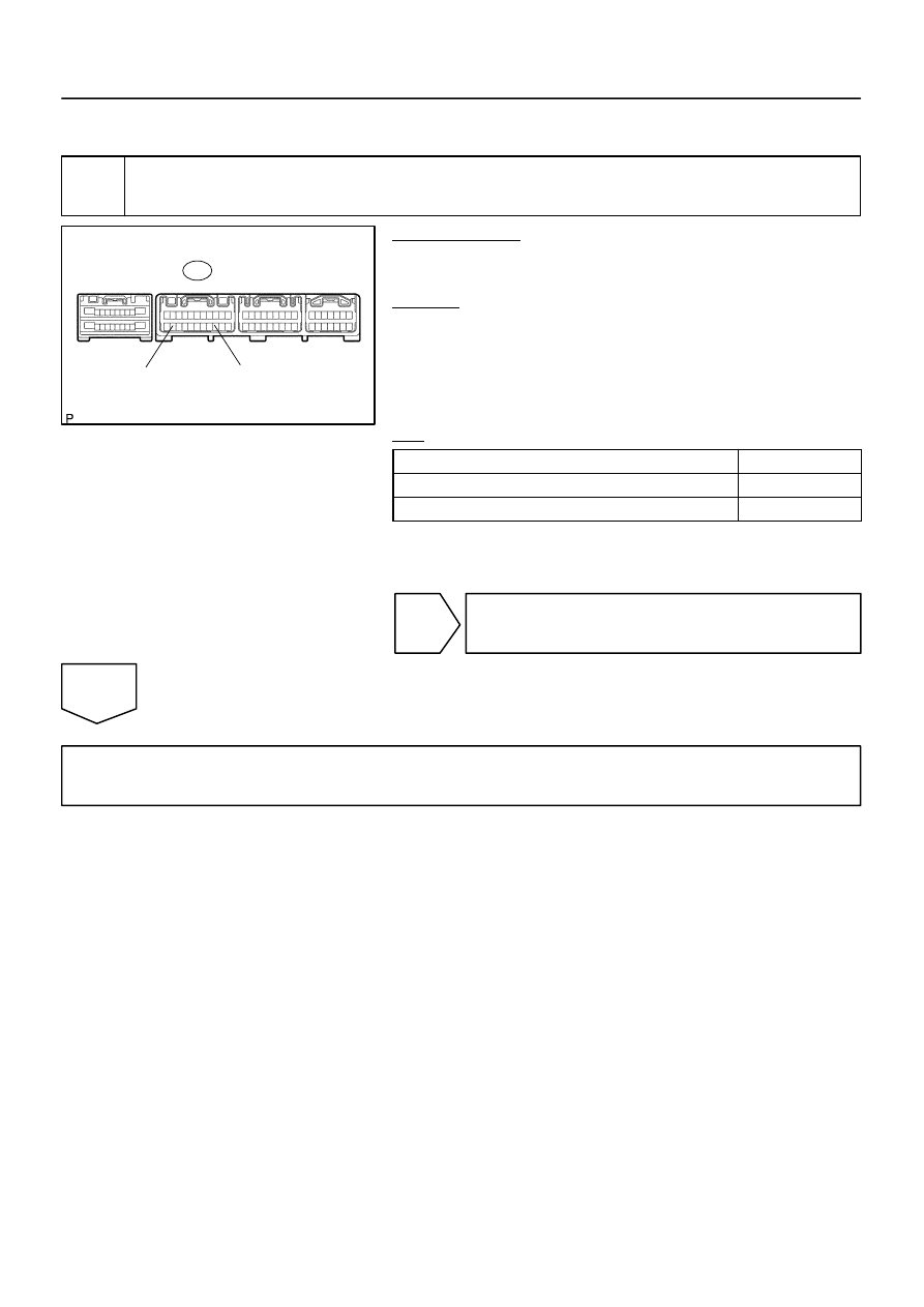
Check voltage between terminals TS and S5–TS of integration control and panel.
PREPARATION:
Remove the integration control and panel with connectors still
connected.
CHECK:
(a)
Turn the ignition switch to ON.
(b)
Measure the voltage between terminals TS and S5–TS of
the integration control and panel connector when the so-
lar sensor is subjected to an electric light, and when the
sensor is covered by a cloth.
OK:
Condition
Voltage
Move the light away from the sensor
Voltage increases
Move the light closer to the sensor
Voltage decreases
HINT:
Use an incandescent lamp for inspection. Bring it within 30 cm
(11.8 in.) of the solar sensor.
NG
OK
Proceed to next circuit inspection shown in problem symptoms table (See page
ever, if DTC 21 is displayed, replace integration control and panel.
I08308
1
2
DI–2338
–
DIAGNOSTICS
AIR CONDITIONING SYSTEM
2532
2
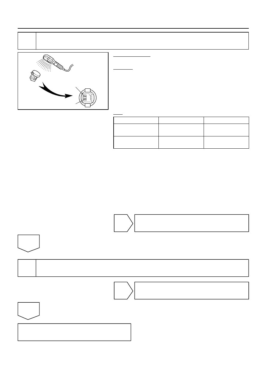
Check solar sensor.
PREPARATION:
Remove the solar sensor.
CHECK:
(a)
Cover the sensor with a cloth.
(b)
Measure the resistance between terminals 1 and 2 of the
solar sensor connector.
HINT:
Connect the positive (+) lead of the ohmmeter to terminal 2 and
the negative (–) lead to terminal 1 of the solar sensor.
OK:
Tester connection
Condition
Specified condition
A15–1 – A15–2
Sensor is subject to elec-
tric light
Except
∞
Ω
A15–1 – A15–2
Sensor is covered with a
cloth
∞
Ω
(No continuity)
NOTICE:
The connection procedure for using a digital tester such as
an TOYOTA electrical tester is shown above. When using
an analog tester, connect the positive (+) lead to terminal
1 and negative (–) lead to terminal 2 of the A/C solar sensor.
HINT:
As the inspection light is moved away from the sensor, the
voltage increases.
Use an incandescent lamp for inspection. Bring it within
30 cm (11.8 in.) of the A/C solar sensor.
NG
Replace solar sensor.
OK
3
Check harness and connector between solar sensor and integration control and
panel (See page
).
NG
Repair or replace harness or connector.
OK
Replace integration control and panel.
Нет комментариевНе стесняйтесь поделиться с нами вашим ценным мнением.
Текст