Toyota Sequoia (2005). Manual — part 636
I28835
24
Y–B
W–R
A3
A/C Magnetic Clutch
and Lock Sensor
2
1
IG4
SG–TAM
Integration Control
and Panel
13
I19 LOCK
20
I19
Y–B
W–R
J14
J/C
A
A
23
Y–B
IG4
–
DIAGNOSTICS
AIR CONDITIONING SYSTEM
DI–2339
2533
DTC
22
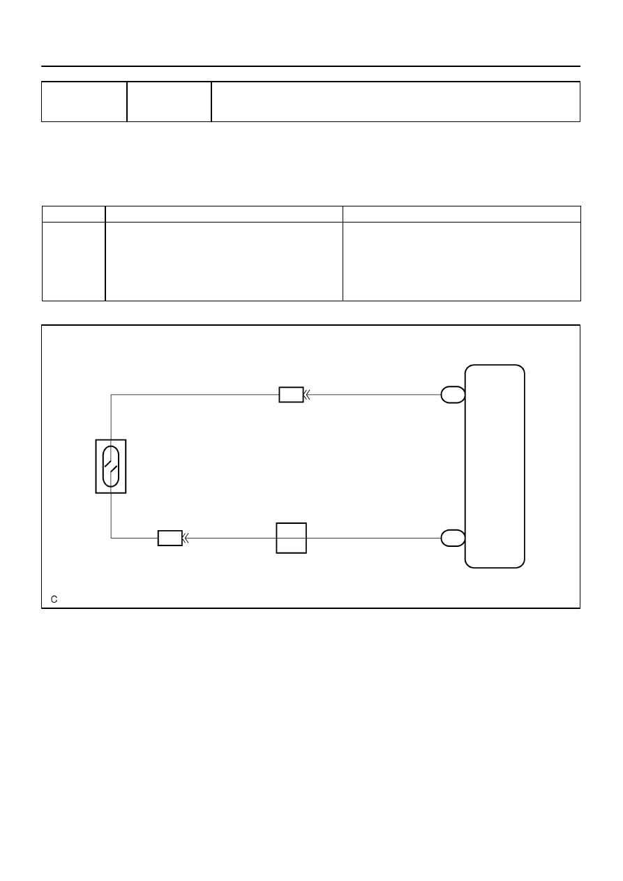
Compressor Lock Sensor Circuit
CIRCUIT DESCRIPTION
This sensor sends 1 pulse per engine revolution to the integration control and panel.
If the compressor speed divided by the engine speed is smaller than a predetermined value, the integration
control and panel turns the compressor OFF. The indicator flashes at about 1 second intervals.
DTC No.
Detection Item
Trouble Area
22
All conditions below are detected for 3 sec. or more
(a) Engine speed: 450 rpm or more
(b) Ratio of engine to compressor speed deviates 20% or more
in comparison to normal operation.
Compressor drive belt
Compressor lock sensor
Compressor
Harness or connector between compressor lock sensor and
integration control and panel
Integration control and panel
WIRING DIAGRAM
DIDKY–01
I05252
2
1
N02774
0.2 V/Din.
LOCK IN signal waveform
0 V
20 msec/Division (Idling)
DI–2340
–
DIAGNOSTICS
AIR CONDITIONING SYSTEM
2534
INSPECTION PROCEDURE
1
Check compressor.
PREPARATION:
(a)
Check and adjust compressor drive belt tension (See page
).
CHECK:
(a)
Check that the compressor does not lock when starting the engine and turning the A/C switch on.
OK: Cooler compressor assy does not lock during operation
HINT:
If the compressor drive belt slips when the A/C switch is on, the magnet clutch seems to be locked.
If the condition continues for more than 3 seconds, the A/C amplifier turns off the magnet clutch for compres-
sor drive belt protection.
NG
Replace compressor.
OK
2
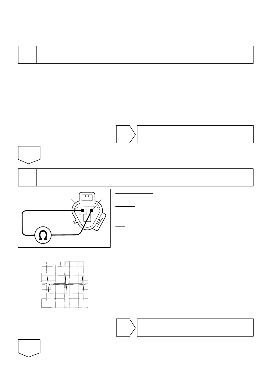
Check compressor lock sensor.
PREPARATION:
Disconnect the compressor connector.
CHECK:
Measure the resistance between terminals 1 and 2 of the com-
pressor lock sensor connector.
OK:
Resistance : 65 to 125
Ω
at 20
°
C (68
°
F)
Reference: Inspection using oscilloscope
During cranking or idling, measure the voltage between termi-
nals LOCK and SG–TAM of the integration control and panel.
HINT:
The correct waveform appears as shown in the illustration on
the left.
NG
Replace compressor.
OK

–
DIAGNOSTICS
AIR CONDITIONING SYSTEM
DI–2341
2535
3
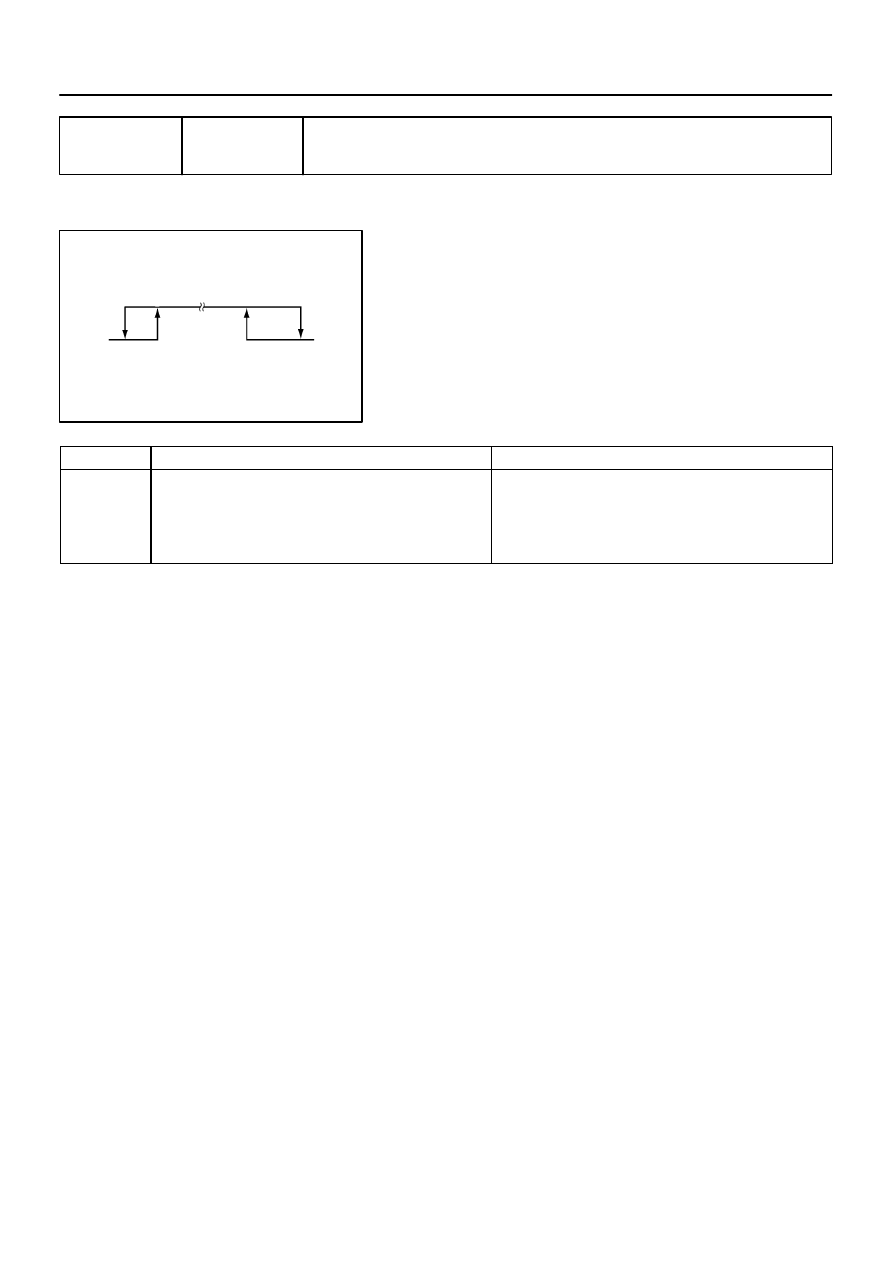
Check harness and connector between compressor lock sensor and integration
control and panel (See page
NG
Repair or replace harness or connector.
OK
Replace integration control and panel.
I29011
ON (Below 1.0
Ω
)
Low pressure side
High pressure side
OFF
(10 k
Ω
or higher)
OFF
(10 k
Ω
or higher)
(2.0 kgf
⋅
cm
2
, 28 psi) (32.0 kgf
⋅
cm
2
, 455 psi)
196 KPa
3,140 KPa
DI–2342
–
DIAGNOSTICS
AIR CONDITIONING SYSTEM
2536
DTC
23
Pressure Switch Circuit
CIRCUIT DESCRIPTION
The pressure switch sends the appropriate signals to the A/C
amplifier when the A/C refrigerant pressure drops too low or
rises too high. When the A/C amplifier receives these signals,
it outputs signals through the A/C amplifier to turn the magnet
clutch relay off and turns the magnetic clutch off.
DTC No.
Detection Item
Trouble Area
23
Open in pressure sensor circuit.
Abnormal refrigerant pressure.
below 196 kPa (2.0 kg/cm
2
, 28 psi)
over 3,140 kPa (32.0 kgf/cm
2
, 455 psi)
Pressure switch
Harness or connector between pressure switch and integra-
tion control and panel
Refrigerant pipe line
Integration control and panel
DI3FD–09
Нет комментариевНе стесняйтесь поделиться с нами вашим ценным мнением.
Текст