Toyota Sequoia (2005). Manual — part 157

–
DIAGNOSTICS
ENGINE
DI–423
617
MONITOR STRATEGY
P2430
Air flow/pressure sensor circuit range check
(Fluctuating)
P2431
Air flow/pressure sensor circuit rationality
Related DTCs
P2432
Air flow/Pressure sensor circuit range check
(Low voltage)
P2433
Air flow/pressure sensor circuit range check
(High voltage)
Required sensors/components
Pressure sensor
Frequency of operation
Continuous
Duration
P2430, P2432, P2433: 0.5 sec.
P2431: 5 sec.
MIL operation
P2430, P2432, P2433: Immediate
P2431: 2 driving cycles
Sequence of operation
None
TYPICAL ENABLING CONDITIONS
It
Specification
Item
Minimum
Maximum
The monitor will run whenever these
DTCs are not present
See page
Starter
OFF
Time after starter turned from ON to OFF
2 sec.
–
Battery voltage
8 V
–
Ignition switch
ON
TYPICAL MALFUNCTION THRESHOLDS
Detection Criteria
Threshold
P2430:
Air pressure sensor voltage
Less than 0.1 V, or more than 4.8 V
P2432:
Air pressure sensor voltage
Less than 0.1 V
P2433:
Air pressure sensor voltage
More than 4.8 V
P2431:
Air pressure
Less than 338 mmHg (45 kPa), or more than 1013 mmHg (135 kPa)
A23557
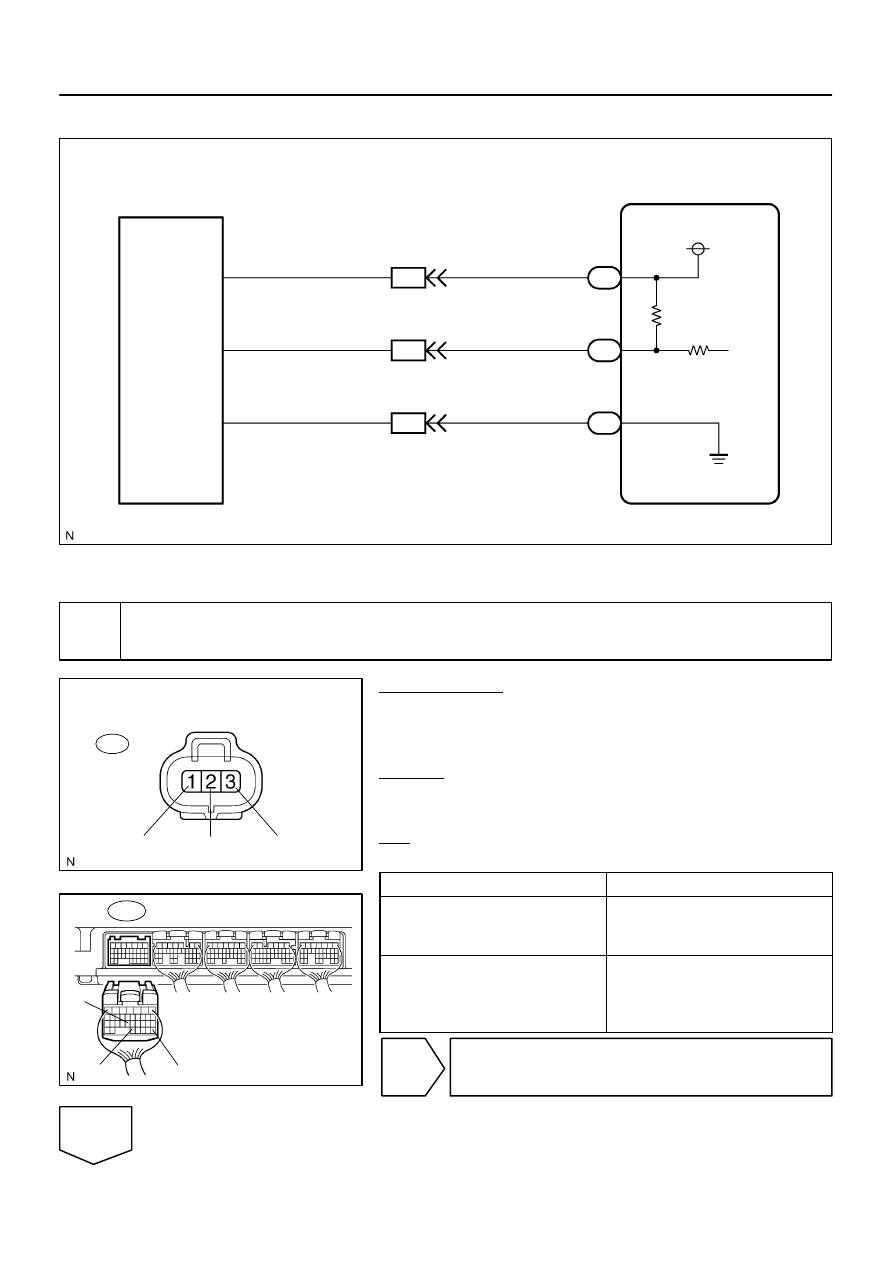
ECM
A42
Air Pressure Sensor
VC
AIP
E2
E8
E8
E8
28
32
23
VC
AIP
E2
EB4
EB4
EB4
G–B
G–B
B–Y
B–Y
G–W
G–W
6
5
1
5 V
B17412
E8
E2
AIP
VC
B17439
Wire Harness Side:
Pressure Sensor Connector
A42
E2
AIP
VC
DI–424
–
DIAGNOSTICS
ENGINE
618
WIRING DIAGRAM
INSPECTION PROCEDURE
1
Check for open and short in harness and connector between pressure sensor
and ECM (See page
).
PREPARATION:
(a)
Remove the intake manifold (see page
).
(b)
Disconnect the A42 pressure sensor connector.
(c)
Disconnect the E8 ECM connector.
CHECK:
Measure the resistance between the wire harness side connec-
tors.
OK:
Standard:
Tester Connection
Specified Condition
VC (A42–1) – VC (E8–23)
AIP (A42–2) – AIP (E8–32)
E2 (A42–3) – AIP (E8–28)
Below 1
Ω
VC (A42–1) or VC (E8–23) –
Body ground
AIP (A42–2) or AIP (E8–32) –
Body ground
10 k
Ω
or higher
NG
Repair or replace harness and connector.
OK
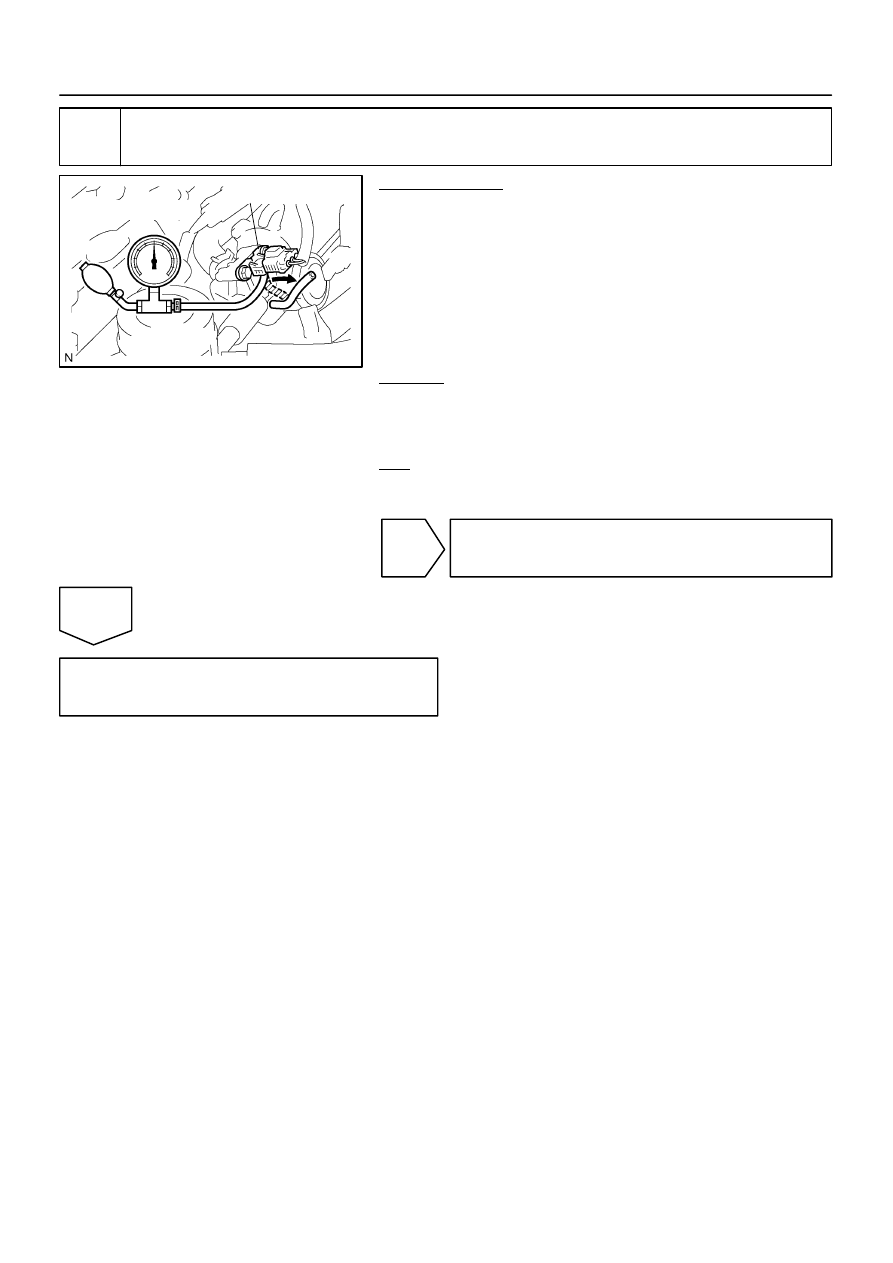
B17434
Pressure Gauge
Pressure Sensor
–
DIAGNOSTICS
ENGINE
DI–425
619
2
Inspect pressure sensor.
PREPARATION:
(a)
Remove the intake manifold (see page
).
(b)
Connect the pressure gauge to the pressure sensor as
shown in the illustration.
(c)
Connect the hand–held tester to the DLC3 on the vehicle.
(d)
Turn the ignition switch ON and push the hand–held tes-
ter main switch ON (Do not start engine).
(e)
Select the following items: DIAGNOSIS / ENHANCED
OBD II / DATA LIST / 2ND AIR PRESS.
CHECK:
Check that the pressure displayed on the hand–held tester fluc-
tuates when applying the pressure to the pressure sensor with
the pressure gauge.
OK:
Pressure fluctuates in response to the pressure ap-
plied with pressure gauge.
NG
Replace pressure sensor (See page
).
OK
Replace ECM (See page

DI–426
–
DIAGNOSTICS
ENGINE
620
DTC
P2444
Secondary Air Injection System Pump Stuck
ON Bank 1
DTC
P2445
Secondary Air Injection System Pump Stuck
OFF Bank 1
CIRCUIT DESCRIPTION
Refer to DTC P0412 on page
.
DTC No.
DTC Detection Condition
Trouble Area
P2444
Air pump stuck ON.
The secondary air pressure is more than 5 kPa (38 mmHg)
despite the ECM ordering the air pump to turn off.
(2 trip detection logic)
Short in air pump circuit
Air injection driver
Pressure sensor
Open or short in pressure sensor circuit
ECM
P2445
Air pump stuck OFF or air injection volume is insufficient.
The amount of air flow is below the criteria.
(The secondary air pressure is less than specified value de-
spite the ECM ordering the air pump turn ON.)
(2 trip detection logic)
Air pump fuse
Vacuum hose
Air pump assembly
Air injection driver
Open in air pump circuit
Air injection system piping
Pressure sensor
Open or short in pressure sensor circuit
ECM
MONITOR DESCRIPTION
P2444:
The ECM observes the pressure in the secondary air passage using the pressure sensor located on the air
switching valve in the secondary air injection system. The sensor measures the pressure in the secondary
air passage and sends a signal to the ECM.
If the pressure level from the sensor exceed a certain level despite the ECM turning off the air pump, the
ECM interprets this as a fault in the secondary air injection system and sets a DTC.
P2445:
The ECM calculates the amount of air flow in the secondary air system based on the output values of the
pressure sensor and mas air flow meter.
The ECM determines whether the amount of air flow is normal or not according to the calculated value. When
the amount of air flow is below the criteria, the ECM stores the DTC and illuminates the MIL.
DIDMU–01
Нет комментариевНе стесняйтесь поделиться с нами вашим ценным мнением.
Текст