Toyota Sequoia (2005). Manual — part 125
A21381
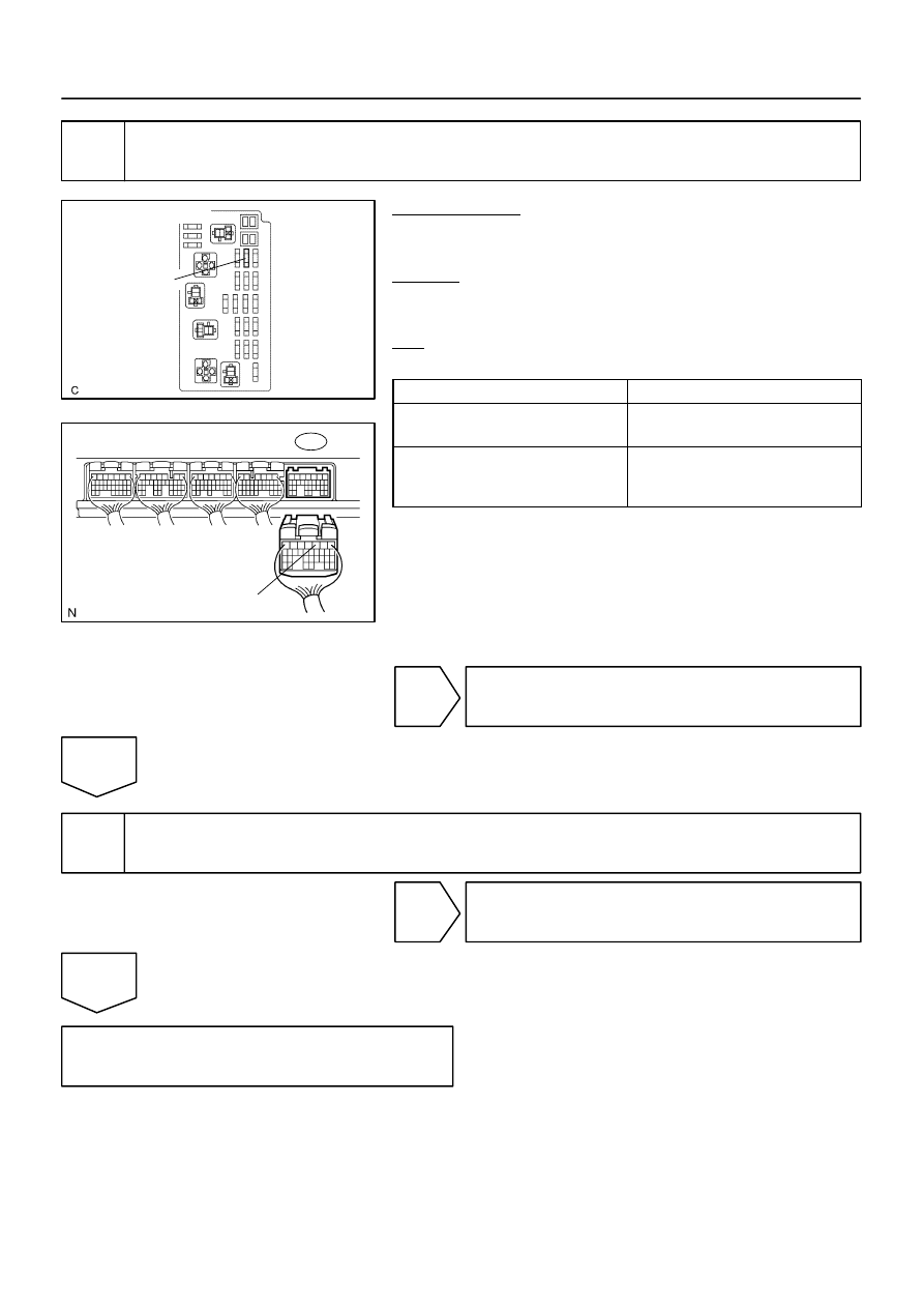
Engine Room J/B
EFI No. 1 Fuse
B17417
E4
BATT
ECM Connector
–
DIAGNOSTICS
ENGINE
DI–295
489
4
Check for open and short in harness and connector between ECM and EFI No. 1
fuse, EFI No. 1 fuse and battery.
PREPARATION:
(a)
Remove the EFI No. 1 fuse from the engine room J/B.
(b)
Disconnect the E4 ECM connector.
CHECK:
Measure the resistance between the wire harness side connec-
tor.
OK:
Standard:
Tester Connection
Specified Condition
Engine Room J/B (EFI No. 1 fuse
terminal 2) – BATT (E4–3)
Below 1
Ω
Engine Room J/B (EFI No. 1 fuse
terminal 2) or BATT (E4–3) –
Body ground
10 k
Ω
or higher
NG
Repair or replace harness or connector.
OK
5
NG
Replace battery.
OK
Check and replace engine room J/B.

DI–296
–
DIAGNOSTICS
ENGINE
490
DTC
P0604
Internal Control Module Random Access
Memory (RAM) Error
DTC
P0606
ECM/PCM Processor
DTC
P0607
Control Module Performance
DTC
P0657
Actuator Supply Voltage Circuit / Open
MONITOR DESCRIPTION
The ECM continuously monitors its internal memory status, internal circuits, and output signals to the throttle
actuator. This self–check insures that the ECM is functioning properly. If any malfunction is detected, the
ECM will set the appropriate DTC and illuminate the MIL.
The ECM memory status is diagnosed by internal ”mirroring” of the main CPU and the sub CPU to detect
RAM (Random Access Memory) errors. The two CPUs also perform continuous mutual monitoring.
The ECM sets a DTC if: 1) outputs from the 2 CPUs are different and deviate from the standards, 2) the sig-
nals to the throttle actuator deviate from the standards, 3) a malfunction is found in the throttle actuator sup-
ply voltage, and 4) any other ECM malfunction is found.
DTC No.
DTC Detecting Condition
Trouble Area
P0604
P0606
P0607
P0657
ECM malfunction
ECM
MONITOR STRATEGY
P0604
Random access memory (RAM) error
R l t d DTC
P0606
CPU malfunction
Related DTCs
P0607
ECM range check
P0657
ETCS power supply
Required sensors/components
ECM
Frequency of operation
Continuous
Duration
Within 1 sec.
MIL operation
Immediate
Sequence of operation
None
TYPICAL ENABLING CONDITIONS
The monitor will run whenever these
DTCs are not present
See page
The typical enabling condition is not avail-
able
–
DI3IK–13

–
DIAGNOSTICS
ENGINE
DI–297
491
TYPICAL MALFUNCTION THRESHOLDS
Detection Criteria
Threshold
P0604:
RAM
RAM check failure
P0606:
Either of the following conditions is met
Condition 1 or 2
1. Difference between TP of main CPU and TP of sub CPU
0.3 V or more
2. Difference between APP of main CPU and APP of sub
CPU
0.3 V or more
P0607:
Either of the following conditions is met
Condition 1 or 2
1. All of the following conditions are met
Condition (a), (b) and (c)
(a) CPU reset
1 time or more
(b) Difference between TP and APP learned
0.4 V or more
(c) Electronic throttle actuator
OFF
2. CPU reset
2 times or more
P0657:
ECTS power supply when ignition switch OFF to ON
7 V or more
INSPECTION PROCEDURE
HINT:
Read freeze frame data using
the hand−held tester.
Freeze frame data records the engine conditions when
a malfunction is detected. When troubleshooting, freeze frame data can help determine if the vehicle was
running or stopped, if the engine was warmed up or not, if the air–fuel ratio was lean or rich, as well as other
data from the time when a malfunction occurred.
Replace ECM (See page

DI–298
–
DIAGNOSTICS
ENGINE
492
DTC
P0617
Starter Relay Circuit High
MONITOR DESCRIPTION
While the engine is being cranked, the battery positive voltage is applied to terminal STA of the ECM.
If the vehicle is being driven and the ECM detects the starter control signal (STA), the ECM concludes that
the starter control circuit is malfunctioning. The ECM will turn on the MIL and a DTC is set.
DTC No.
DTC Detection Condition
Trouble Area
P0617
When all conditions (a), (b) and (c) are satisfied for 20 seconds
with battery (+B) voltage 10.5 V or more
(a) Vehicle speed
20 km/h (12.4 mph)
(b) Engine revolution
1,000 rpm
(c) STA signal ON
Park/neutral position switch
Starter relay circuit
Ignition switch
ECM
MONITOR STRATEGY
Related DTCs
P0617
Starter signal error
R
i d
/
t
Main sensors/components
Starter signal
Required sensors/components
Related sensors/components
Vehicle speed sensor, Engine speed sensor
Frequency of operation
Continuous
Duration
20 sec.
MIL operation
Immediate
Sequence of operation
None
TYPICAL ENABLING CONDITIONS
It
Specification
Item
Minimum
Maximum
The monitor will run whenever this DTC is
not present
See page
Battery voltage
10.5 V
–
Vehicle speed
20 km/h (12.4 mph)
–
Engine RPM
1,000 rpm
–
TYPICAL MALFUNCTION THRESHOLDS
Detection Criteria
Threshold
Starter signal
ON (at ”more than 20 km/h (12.4 mph) and more than 1,000 rpm”)
DID8D–01
Нет комментариевНе стесняйтесь поделиться с нами вашим ценным мнением.
Текст