Nissan Primera P12. Manual — part 174
COMBINATION METERS (LHD MODELS)
DI-25
C
D
E
F
G
H
I
J
L
M
A
B
DI
The Fuel Gauge Does Not Work
EKS009AI
1.
HARNESS CONNECTOR INSPECTION
1.
Turn the ignition switch OFF.
2.
Check combination meter, fuel level sensor unit and terminals (meter side, and harness side) for poor
connection and bend.
OK or NG
OK
>> GO TO 2.
NG
>> Repair connector.
2.
CHECK INSTALLATION CONDITION
Check fuel level sensor unit installation (refer to
FL-8, "FUEL LEVEL SENSOR UNIT (YD22DDTi)"
or
"FUEL LEVEL SENSOR UNIT (F9Q)"
), and check whether the float arm interferes or binds with any compo-
nents inside the arm.
OK or NG
OK
>> Recheck “PRELIMINARY CHECK”.
NG
>> Check fuel level sensor unit. Refer to
DI-26, "Electrical Components Inspection"
.
DI-26
COMBINATION METERS (LHD MODELS)
Electrical Components Inspection
EKS009AJ
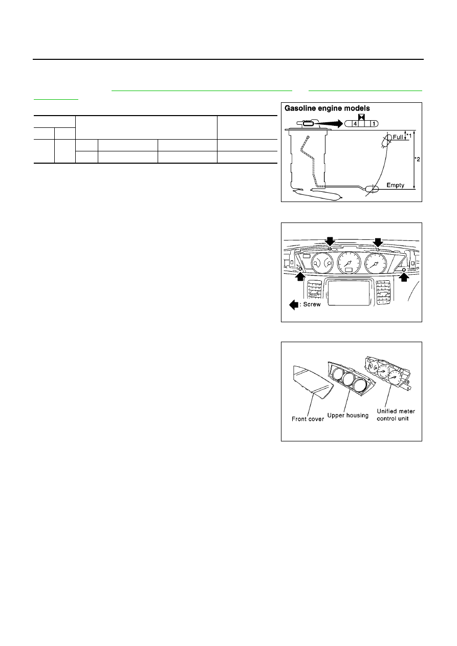
FUEL LEVEL SENSOR UNIT CHECK
For removal, refer to
FL-8, "FUEL LEVEL SENSOR UNIT (YD22DDTi)"
or
for Gasoline engine models.
Check the resistance between terminals 1 and 4.
*1 and *2: When float rod is in contact with stopper.
Removal and Installation for Combination Meter
EKS009AK
1.
Remove the cluster lid A. Refer to IP section in P12 ESM
(SM2E00-1P12E0E).
2.
Remove the screws (4), and pull out combination meter.
3.
Disconnect connectors and remove combination meter.
Disassembly and Assembly for Combination Meter
EKS009AL
1.
Disengage the tabs (8) to separate front cover.
2.
Remove upper housing.
Ohmmeter
Float position
mm (in)
Resistance
value
(
Ω
)
(+)
(
−
)
4
1
*1
Full
35 (1.38)
Approx. 4.5 - 5.5
*2
Empty
179 (7.05)
Approx. 80 - 83
SKIA0904E
SKIA0332E
SKIA0333E
COMBINATION METERS (RHD MODELS)
DI-27
C
D
E
F
G
H
I
J
L
M
A
B
DI
COMBINATION METERS (RHD MODELS)
PFP:24810
System Description
EKS009AM
UNIFIED CONTROL METER
●
Speedometer, odo/trip meter, tachometer, fuel gauge and water temperature gauge are controlled totally
by control unit built in combination meter.
●
Signal of speedometer, odo/trip meter, tachometer and water temperature gauge are received via CAN
communication line.
●
Digital meter is adopted for odo/trip meter.*
*The record of the odometer is kept even if the battery cable is disconnected. The record of the trip meter
is erased when the battery cable is disconnected.
●
Odo/trip meter, A/T indicator and ICC system display segments can be checked in self-diagnosis mode.
●
Meter/gauge can be checked in self-diagnosis mode.
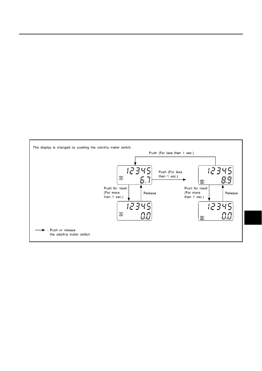
HOW TO CHANGE THE DISPLAY FOR ODO/TRIP METER
●
The CAN communication signals (vehicle speed signal) from ESP/TCS/ABS control unit or ABS actuation
and electric unit, and the memory signals from the meter memory circuit are processed by the combina-
tion meter, and the mileage is displayed.
●
Operating the odometer/trip switch allows switching the mode in the following order.
●
The odo/trip meter display switching and trip display resetting can be identified by the time from pressing
the odo/trip meter switch to releasing it.
●
When resetting with trip A displayed, only trip A display is reset (same as trip B).
POWER SUPPLY AND GROUND CIRCUIT
Power is supplied at all times
●
through 10A fuse [NO. 12, located in the fuse block (J/B)]
●
to combination meter terminal 39.
With the ignition switch in the ON or START position, power is supplied
●
through 10A fuse [NO. 30, located in the fuse block (J/B)]
●
to combination meter terminal 38.
With the ignition switch in the ACC or ON position, power is supplied
●
through 10A fuse [NO. 1, located in the fuse block (J/B)]
●
to combination meter terminal 37.
Ground is supplied
●
to combination meter terminals 11, 12 and 32
●
through body grounds M16, M50, M70 and F115 (Gasoline engine models) or
SEL175W
DI-28
COMBINATION METERS (RHD MODELS)
●
through body grounds M16, M50 and M70 (Diesel engine models).
WATER TEMPERATURE GAUGE
The water temperature gauge indicates the engine coolant temperature.
ECM provides a water temperature signal to combination meter for water temperature gauge with CAN com-
munication line.
TACHOMETER
The tachometer indicates engine speed in revolution per minutes (rpm). ECM provides an engine speed signal
to combination meter for tachometer with CAN communication line.
FUEL GAUGE
The fuel gauge indicates the approximate fuel level in the fuel tank.
The fuel gauge is regulated by a variable resistor signal supplied
●
to combination meter terminal 34 for the fuel level sensor
●
from terminal 4 of the fuel level sensor unit
●
through terminal 1 of the fuel level sensor unit and
●
through combination meter terminal 33
SPEEDOMETER
ESP/TCS/ABS control unit or ABS actuator and electric unit provides a vehicle speed signal to the combina-
tion meter for the speedometer with CAN communication line.
Нет комментариевНе стесняйтесь поделиться с нами вашим ценным мнением.
Текст