Nissan Primera P12. Manual — part 172
COMBINATION METERS (LHD MODELS)
DI-17
C
D
E
F
G
H
I
J
L
M
A
B
DI
Combination Meter Calibration
After replacing a combination meter, it might be necessary to calibrate the fuel gauge/low fuel warning lamp. In
case the fuel warning lamp is flashing after replacing the combination meter perform the following:
1.
Press both reset buttons.
2.
Turn the ignition ON and keep the reset buttons depressed for at least 5 seconds.
3.
Release both reset buttons.
The low fuel warning lamp will stop flashing and the combination meter will shown CALL and possibly
CALL FAIL. Showing CALL FAIL does not indicate a concern as this might be related to the current (unex-
pected) amount of fuel in the tank.
Trouble Diagnoses
EKS009A9
PRELIMINARY CHECK
1.
CHECK WARNING LAMPS
1.
Turn ignition switch ON.
2.
Warning lamps should illuminate (seat belt warning or door warning etc.).
Do warning lamps illuminate?
YES
>> GO TO 2.
NO
>> Power supply and ground check. Refer to
DI-20, "Power Supply and Ground Circuit Check"
.
2.
CHECK SELF-DIAGNOSIS MODE OPERATION
Perform self-diagnosis mode. Refer to
DI-14, "PERFORMING SELF-DIAGNOSIS MODE"
.
Can self-diagnosis mode be activated?
YES
>> GO TO 3.
NO
>> Replace unified meter control unit. Refer to
DI-26, "Removal and Installation for Combination
.
3.
CHECK METER/GAUGE OPERATION
Check meter/gauge operation in self-diagnosis mode (Meter/gauge test). Refer to
.
Is any malfunction indicated in self-diagnosis mode?
YES
>> GO TO “Symptom Chart 1”. Refer to
.
NO
>> GO TO 4.
4.
CHECK SEGMENTS
Check all odo/trip meter segments in self-diagnosis mode (Odo/trip meter segment test). Refer to
"PERFORMING SELF-DIAGNOSIS MODE"
.
Is any malfunction indicated in self-diagnosis mode?
YES
>> GO TO “Symptom Chart 1”. Refer to
.
NO
>> GO TO 5.
5.
CHECK FUEL WARNING LAMP
Check fuel warning lamp in self-diagnosis mode (Fuel warning lamp test). Refer to
.
Does fuel warning lamp illuminate?
YES
>> GO TO “Symptom Chart 1”. Refer to
.
NO
>> GO TO 6.

DI-18
COMBINATION METERS (LHD MODELS)
6.
CHECK INPUT SIGNALS
Check input signals from each sensors in self-diagnosis mode (Error 1 and Error E). Refer to
.
OK or NG
OK
>> GO TO 7.
NG
>> GO TO “Symptom Chart 2”. Refer to
.
7.
CHECK OTHER MALFUNCTION
Check each malfunction according to the instruction of the “SYMPTOM CHART 3”. Refer to
.
OK or NG
OK
>> Combination meter is OK.
NG
>> Check the case of malfunction.
COMBINATION METERS (LHD MODELS)
DI-19
C
D
E
F
G
H
I
J
L
M
A
B
DI
SYMPTOM CHART
Symptom Chart 1
Symptom Chart 2
Symptom Chart 3
Symptom
Possible causes
Repair order
Odo/trip meter indicates mal-
function in Diagnosis mode.
Unified meter control unit
Replace unified meter control unit. Refer to
Installation for Combination Meter"
.
Multiple meter/gauge indi-
cate malfunction in Diagno-
sis mode.
One of speedometer/tachom-
eter/fuel gauge/water temp.
gauge indicates malfunction
in Diagnosis mode.
Symptom
Possible causes
Repair order
Speedometer input signal
indicates malfunction in Diag-
nosis mode.
Speedometer input signal
Check signal for speedometer. Refer to
Speed Signal (With ESP/TCS/ABS Control System)"
or
"Inspection/Vehicle Speed Signal (Without ESP/TCS/ABS Control
System)"
.
Tachometer input signal indi-
cates malfunction in Diagno-
sis mode.
Tachometer input signal
Check signal for tachometer. Refer to
.
Fuel level input signal indi-
cates malfunction in Diagno-
sis mode.
Fuel level input signal
Check signal for tachometer. Refer to
.
Water temperature input sig-
nal Indicates malfunction in
Diagnosis mode.
Water temp. gauge input signal
Check signal for water temp. gauge. Refer to
.
Reset buttons indicates mal-
function in Diagnosis mode.
Unified meter control unit
Replace unified meter control unit assembly. Refer to
"Removal and Installation for Combination Meter"
.
CPU indicates malfunction in
Diagnosis mode.
Unified meter control unit
Replace unified meter control unit assembly. Refer to
"Removal and Installation for Combination Meter"
.
Symptom
Possible causes
Repair order
Fuel gauge pointer fluctuates,
Indicator wrong value or var-
ies.
-
Check the case of malfunction. Refer to
Pointer Fluctuates Indicator Wrong Value or Varies"
.
Fuel gauge does not move to
“F” position.
-
Check the case of malfunction. Refer to
.
Fuel gauge does not work.
-
Check the case of malfunction. Refer to
.
DI-20
COMBINATION METERS (LHD MODELS)
Power Supply and Ground Circuit Check
EKS009AA
1.
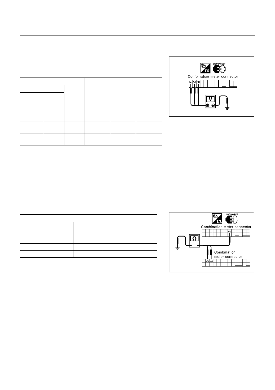
POWER SUPPLY CIRCUIT CHECK
1.
Disconnect combination meter connector.
2.
Check voltage between combination meter harness connector
and ground in the following conditions.
OK or NG
OK
>> GO TO 2.
NG
>> Check the following.
●
10A fuse [No. 1, located in fuse block (J/B)].
●
10A fuse [No. 30, located in fuse block (J/B)].
●
10A fuse [No. 12, located in fuse block (J/B)].
●
Harness for open or short between fuse and combination meter.
2.
GROUND CIRCUIT CHECK
Check continuity between combination meter and ground in the following conditions.
OK or NG
OK
>> INSPECTION END.
NG
>> Harness for open ground circuit.
Terminals
Ignition switch position
(+)
(
−
)
OFF
ACC
ON
Connector
Terminal
(wire
color)
M37
50 (P)
Ground
0V
Battery
voltage
Battery
voltage
M37
51 (Y)
Ground
0V
0V
Battery
voltage
M37
52 (R/B)
Ground
Battery
voltage
Battery
voltage
Battery
voltage
MKIB0035E
Terminals
Continuity
(+)
(
−
)
Connector
Terminal
M36
25
Ground
Yes
M37
45
Ground
Yes
M36
24
Ground
Yes
MKIB0036E
Нет комментариевНе стесняйтесь поделиться с нами вашим ценным мнением.
Текст