Chrysler 300M, Dodge Interpid. Manual — part 95
COURTESY LAMP
DESCRIPTION
The Body Control Module (BCM) illuminates the
courtesy lamps whenever a door is opened. When the
last door is closed, the BCM “fades-to-OFF” the cour-
tesy lamps in five seconds if not in illuminated entry
mode. If a door is left ajar, the courtesy lamps
remain on for a maximum of 15 minutes when the
ignition switch is OFF. After 15 minutes, the BCM
“fades-to-OFF” the courtesy lamps.
GLOVE BOX LAMP
REMOVAL
(1) Open hood and disconnect the negative battery
cable remote terminal from the remote battery post.
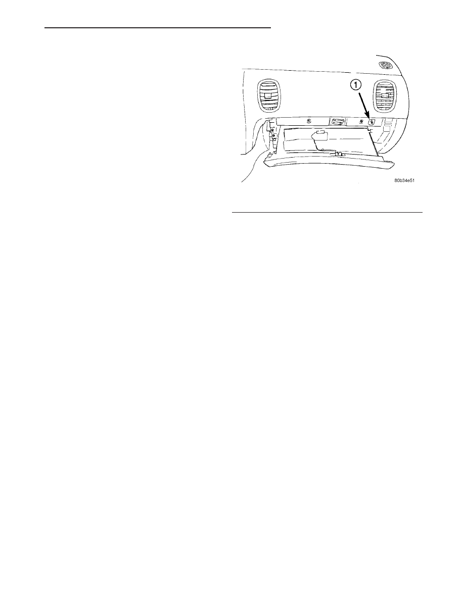
(2) Open the glove box door, using a trim stick
(special tool #C-4755) or equivalent, gently pry out on
the glove box lamp/switch assembly from upper right
hand corner of opening.
(3) Pull defective bulb out of lamp socket.
INSTALLATION
(1) Push replacement bulb into the lamp socket.
(2) Place glove box lamp/switch assembly into posi-
tion, firmly snap into place, and close the glove box
door.
(3) Connect the negative battery cable remote ter-
minal to the remote battery post.
GLOVE BOX LAMP SWITCH
REMOVAL
(1) Open hood and disconnect the negative battery
cable remote terminal from the remote battery post
(Fig. 9).
(2) Open the glove box door, using a trim stick
(special tool #C-4755) or equivalent, gently pry out on
the glove box lamp/switch assembly from upper right
hand corner of opening (Fig. 4).
(3) Disconnect the wire connector.
INSTALLATION
(1) Connect the electrical connector to the new
glove box lamp/switch.
(2) Place glove box lamp/switch assembly into posi-
tion, firmly snap into place (Fig. 4), and close the
glove box door.
(3) Connect the negative battery cable remote ter-
minal to the remote battery post.
ILLUMINATED ENTRY
DESCRIPTION
The Illuminated Entry System is available on vehi-
cles equipped with the Remote Keyless Entry (RKE)
system. The Illuminated Entry System turns ON the
courtesy lamps when the remote keyless entry sys-
tem is activated.
OPERATION
The Remote Keyless Entry Module and the Body
Control Module (BCM) are used to control the sys-
tem. Courtesy lamps will turn on for 30 seconds and
“fade-to-OFF” over a five second period.
The Illuminated Entry System also turns ON the
courtesy lamps when a door is opened. The courtesy
lamps will remain ON while the door is open, then
“fade-to-OFF” 30 seconds after the last door is closed.
The courtesy lamps will “fade-to-OFF” immediately
when the ignition is switched to ON.
The Illuminated Entry System cannot be activated
during the 30 second period after the ignition switch
is turned OFF except by using the RKE transmitter.
If a door is opened and closed during this 30 second
period,
the
system
will
function
as
previously
described.
The courtesy lamps will “fade-to-OFF” immediately
if the RKE lock function is actuated with all the
doors closed.
Fig. 4 Glove Box Lamp/Switch
1 - GLOVE BOX LAMP
LH
LAMPS/LIGHTING - INTERIOR
8L - 49
DIAGNOSIS AND TESTING - ILLUMINATED
ENTRY
When testing the system, all doors must be closed
to prevent courtesy lamps from lighting. Verify that
remote keyless entry system is operating properly
before testing illuminated entry circuits. The body
controller uses input from the remote keyless entry
system to switch ON the courtesy lamps.
Refer to Wiring Diagrams, for component location
and circuit information. Refer to the proper Body
Diagnostic Procedures manual for complete diagnos-
tic information.
TRANSMISSION RANGE
INDICATOR ILLUMINATION
DESCRIPTION
The floor console mounted Transmission Range
Indicator Lamp display utilizes electroluminescent
technology as the light source. The only diagnostics
that should be performed is to check for the presence
of 12 volts on the mating wire harness connector. The
electroluminescent lamp requires a 120 volt AC sig-
nal that is provided by a power converter included in
the assembly. Because of a potential shock hazard,
diagnostics testing of the electroluminescent lamp
and power converter should be avoided. The module
is not serviceable. Refer to Body, Floor Console Shift
Bezel Removal and Installation.
8L - 50
LAMPS/LIGHTING - INTERIOR
LH
ILLUMINATED ENTRY (Continued)
MESSAGE SYSTEMS
TABLE OF CONTENTS
page
page
OVERHEAD CONSOLE
. . . . . . . . . . . . . . . . . . . . . . . . . . 1
. . . . . . . . . . . . . . . . . . . . . . . . . . . . 1
DIAGNOSIS AND TESTING - OVERHEAD
. . . . . . . . . . . . . . . . . . . . . . . . . . . . 1
STANDARD PROCEDURE - MODULE LAMP
REPLACEMENT . . . . . . . . . . . . . . . . . . . . . . . 2
LAMP REPLACEMENT . . . . . . . . . . . . . . . . . . 3
STANDARD PROCEDURE - MODULE LENS
REPLACEMENT . . . . . . . . . . . . . . . . . . . . . . . 3
CALIBRATION . . . . . . . . . . . . . . . . . . . . . . . . . 3
DEMAGNETIZING . . . . . . . . . . . . . . . . . . . . . . 3
VARIATION ADJUSTMENT . . . . . . . . . . . . . . . . 4
STANDARD PROCEDURE - ELECTRONIC
VEHICLE INFORMATION CENTER
PROGRAMMING . . . . . . . . . . . . . . . . . . . . . . . 5
. . . . . . . . . . . . . . . . . . . . . . . . . . 7
. . . . . . . . . . . . . . . . . . . . . . . . 7
COMPASS/MINI-TRIP COMPUTER
. . . . . . . . . . . . . . . . . . . . . . . . . . 8
. . . . . . . . . . . . . . . . . . . . . . . . . . . . 8
DIAGNOSIS AND TESTING - COMPASS
. . . . . . . . . . . . . . . . . . 8
. . . . . . . . . . . . . . . . . . . . . . . . . . . . . 9
. . . . . . . . . . . . . . . . . . . . . . . . . . 9
ELECTRONIC VEHICLE INFO CENTER
. . . . . . . . . . . . . . . . . . . . . . . . . 10
. . . . . . . . . . . . . . . . . . . . . . . . . . . 11
DIAGNOSIS AND TESTING - ELECTRONIC
STANDARD PROCEDURE - TIRE PRESSURE
. . . . . . . . . . . . . . . . . . . . . . . 12
. . . . . . . . . . . . . . . . . . . . . . . . . . . . . 13
. . . . . . . . . . . . . . . . . . . . . . . . . 13
UNIVERSAL TRANSMITTER
. . . . . . . . . . . . . . . . . . . . . . . . . 13
. . . . . . . . . . . . . . . . . . . . . . . . . . . 14
DIAGNOSIS AND TESTING - UNIVERSAL
. . . . . . . . . . . . . . . . . . . . . . . 14
UNIVERSAL TRANSMITTER CODES . . . . . . . 14
UNIVERSAL TRANSMITTER CODES . . . . . . . 14
AMBIENT TEMPERATURE SENSOR
. . . . . . . . . . . . . . . . . . . . . . . . . 15
. . . . . . . . . . . . . . . . . . . . . . . . . . . 15
DIAGNOSIS AND TESTING - AMBIENT
. . . . . . . . . . . . . . . 15
. . . . . . . . . . . . . . . . . . . . . . . . . . . . . 15
. . . . . . . . . . . . . . . . . . . . . . . . . 16
OVERHEAD CONSOLE
DESCRIPTION
The overhead consoles on LH models can include
the Electronic Vehicle Information Center (EVIC)
system (Fig. 2) or the Overhead Travel Information
System (OTIS) (Fig. 1). All overhead consoles are
equipped with two reading and courtesy lamps. Vehi-
cles equipped with a power sunroof, will have the
sunroof control switch located between the two read-
ing and courtesy lamps. The overhead console is
mounted with one screw and two snap clips to a
molded plastic retainer bracket located above the
headliner.
OPERATION
Refer to the vehicle Owner’s Manual for specific
operation of each overhead console and its systems.
DIAGNOSIS AND TESTING - OVERHEAD
CONSOLE
The most reliable, efficient, and accurate means to
diagnose the overhead console or related system
requires the use of a DRB III
t scan tool and the Ser-
vice and Body Diagnostic Procedures Manuals. The
DRB III
t scan tool can provide vital information to
the technician trying to find a problem with a over-
head console component. Diagnostic logic is built into
the overhead console mounted module to help the
person trying to locate the problem by the most effi-
cient means possible. Anytime a problem is sus-
pected, a DRB III
t scan tool must be obtained and
used to retrieve any stored fault codes in the module.
If diagnostic fault codes are present in the module,
record them on a piece of paper immediately before
proceeding any further. Then, use these fault codes to
identify the problem by verifying the fault code.
LH
MESSAGE SYSTEMS
8M - 1

Example, If the module records “TIRE PRESSURE
N/A” fault, locate the diagnostic procedure for this
code in the appropriate Body Diagnostic Procedures
Manual and follow the flow chart until the specific
problem is located and resolved. Once the problem is
thought to be corrected, erase the stored fault code
using the DRB III
t scan tool and verify correct sys-
tem operation. If the tire pressure monitoring system
is functioning correctly, verify that there are no other
stored codes in the module and return the vehicle to
service.
If the fault code could not be verified, such as not
finding anything wrong when following the diagnos-
tic flow chart in the Body Diagnostic Procedures
Manual. This is a good indication that a INTERMIT-
TENT problem may be present. You must than
attempt to find the intermittent problem, such as
running a tire pressure monitoring system self test.
Refer to the Tires/Wheels section for more informa-
tion. Always, eliminate all other potential problems
before attempting to replace the module.
TESTING VOLTAGE AND GROUND SUPPLY TO
OVERHEAD CONSOLE
(1) Remove the overhead console from the head-
liner (Refer to 8 - ELECTRICAL/OVERHEAD CON-
SOLE - REMOVAL) Disconnect the overhead console
electrical connector. Check the fused B(+) circuit in
the overhead console electrical connector. If OK, go to
Step 2. If not OK, repair the open circuit or compo-
nent as required. Refer to the Wiring section for
detailed schematics.
(2) Check the IGN RUN B(+) circuit in the over-
head console electrical connector. If OK, go to Step 3.
If not OK, repair the open IGN RUN B(+) circuit as
required.
(3) Check the Ground circuit in the overhead con-
sole electrical connector. If OK, go to Step 4. If not
OK, repair the open ground circuit as required.
(4) If the tire pressure monitoring system is not
operating properly, refer to the Tires/Wheels section
for more information on the tire pressure monitoring
system.
NOTE: If the compass functions, but accuracy is
suspect, it may be necessary to perform a variation
adjustment. This procedure allows the compass
unit to accommodate variations in the earth’s mag-
netic field strength, based on geographic location.
Refer to Compass Variation Adjustment in the Stan-
dard Procedures section of this group.
NOTE: If the compass reading displays dashes, and
only “CAL” appears in the display, demagnetizing
may be necessary to remove excessive residual
magnetic fields from the vehicle. Refer to Compass
Demagnetizing in the Standard Procedures section
of this group.
STANDARD PROCEDURE
STANDARD PROCEDURE - MODULE LAMP
REPLACEMENT
(1) Remove the overhead console (Refer to 8 -
ELECTRICAL/OVERHEAD CONSOLE - REMOV-
AL).
(2) Using a flat blade screwdriver twist out socket/
lamp (Fig. 3).
(3) Replace lamp(s) as necessary.
Fig. 1 Overhead Console Without Universal
Transmitter
Fig. 2 Overhead Console With Universal Transmitter
8M - 2
MESSAGE SYSTEMS
LH
OVERHEAD CONSOLE (Continued)
Нет комментариевНе стесняйтесь поделиться с нами вашим ценным мнением.
Текст