Chrysler 300M, Dodge Interpid. Manual — part 93
(4) Check for B+ power at the spot lamp bulb with
switch turned ON (Refer to 8 - ELECTRICAL/
LAMPS/LIGHTING
-
EXTERIOR/SPOT
LAMP -
REMOVAL). If there is B+ power at the spot lamp
bulb connector, replace bulb. If there is not B+ power
present, refer to Step 5.
(5) If there is not B+ power present at the spot
lamp with the switch turned on, check circuit for an
open. Possibly the connector in the A-pillar. Refer to
Wiring Diagrams for circuit information.
(6) If there is B+ power at the spot lamp connec-
tor, and no B+ power at the spot lamp bulb, then the
switch is defective within the spot lamp assembly
and the entire unit must be replaced. (Refer to 8 -
ELECTRICAL/LAMPS/LIGHTING
-
EXTERIOR/
SPOT LAMP - REMOVAL).
(7) If lamp still does not light, remove the handle
(Refer to 8 - ELECTRICAL/LAMPS/LIGHTING -
EXTERIOR/SPOT LAMP - REMOVAL), and check
the contact on the shaft end of the head assembly
into the handle to make sure the contact is not dam-
aged.
IF SPOT LAMP IS HARD TO TURN
(1) Check that the head housing clamping screw
creates just enough drag to hold the spot lamp head
in position in windy conditions. Extreme drag will
require more force on the handle to move the spot
lamp head and cause damage.
REMOVAL
CAUTION: Make sure that fuse F (master spot lamp
feed) or either fuse X or Y (left or right spot lamp
feed) are removed from the Power Distribution Cen-
ter (PDC) before performing service on the spot
lamps.
(1) Remove the fuse cover and pull either the X or
Y fuse, depending on which spot lamp is being ser-
viced.
(2) Raise the spot lamp from the stowed to the
operating position.
(3) Using a trim stick (special tool #C-4755) or
equivalent, gently pry out on the A-pillar trim to
release it. This will allow access to the spot lamp
electrical connector.
(4) Remove the instrument panel end cap.
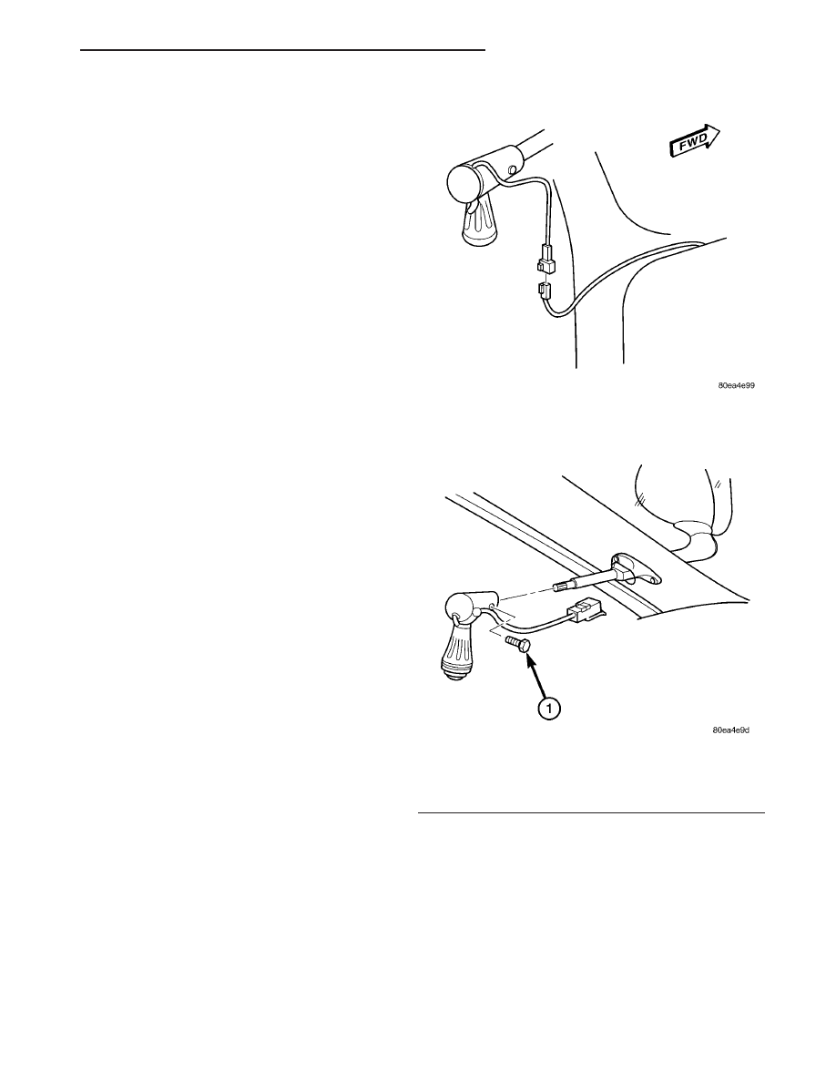
(5) Disconnect the spot lamp electrical connector
(located behind the instrument panel endcap) (Fig.
53).
(6) Loosen, but do not remove the bolt retaining
the handle to the outer tube (Fig. 54).
NOTE: Do not remove the bolt all the way.
(7) Using a plastic tipped hammer, gently tap the
head of the handle retaining bolt (Fig. 54) and the
opposing wedge nut.
(8) Remove the handle from the outer tube.
(9) Remove the A-pillar trim from the spot lamp
outer tube.
CAUTION: Support the head of the spot lamp while
loosening the head assembly clamp screw.
Fig. 53 SPOT LAMP ASSEMBLY ELECTRICAL
CONNECTOR
Fig. 54 SPOT LAMP ASSEMBLY HANDLE
RETAINING BOLT - LOOSEN/TIGHTEN
1 - SPOT LAMP HANDLE RETAINING BOLT
LH
LAMPS/LIGHTING - EXTERIOR
8L - 41
SPOT LAMP ASSEMBLY - POLICE (Continued)
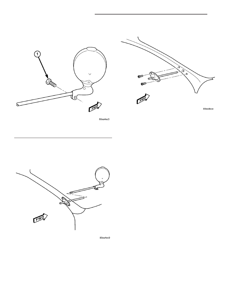
(10) Loosen the clamp screw at the base of the
spot lamp head assembly (Fig. 55).
(11) Carefully remove the spot lamp head with the
intermediate and inner shafts from the outer tube
and mounting bracket (Fig. 56).
(12) Remove the screws retaining the spot lamp
mounting bracket to the A-pillar (Fig. 57).
(13) Remove the spot lamp outer tube and mount-
ing bracket from the A-pillar (Fig. 57).
INSTALLATION
CAUTION: Make sure that fuse F (master spot lamp
feed) or either fuse X or Y (left or right spot lamp
feed) are removed from the Power Distribution Cen-
ter (PDC) before performing service on the spot
lamps.
(1) Install the spot lamp outer tube and mounting
bracket to the A-pillar (Fig. 57).
(2) Install the screws retaining the spot lamp
mounting bracket to the A-pillar (Fig. 57) and tighten
to 33 N·m (29 in. lbs.).
(3) Carefully lift the edge of the secondary door
seal along the windshield pillar to expose the spot
lamp outer tube and apply a small amount of clear
silicone sealer to the base of the outer tube.
(4) Carefully install the spot lamp head with the
intermediate and inner shafts to the outer tube and
mounting bracket until the head assembly bottoms
out on the outer tube (Fig. 56).
(5) Tighten the clamp screw at the base of the spot
lamp head assembly in small incriments while test-
ing the effort required to rotate the spot lamp
between the stowed and operating positions. Stop
tightening the clamp screw when the spot lamp can
maintain any desired position (Fig. 55).
(6) Position the A-pillar trim to the spot lamp
outer tube.
CAUTION: Support the head of the spot lamp while
tightening the head assembly clamp screw. Main-
tain an operating or vertical position.
(7) Install the handle to the outer tube.
Fig. 55 SPOT LAMP HEAD ASSEMBLY
1 - SPOT LAMP HEAD CLAMP SCREW
Fig. 56 SPOT LAMP HEAD ASSEMBLY - REMOVE/
INSTALL
Fig. 57 SPOT LAMP MOUNTING BRACKET -
REMOVE/INSTALL
8L - 42
LAMPS/LIGHTING - EXTERIOR
LH
SPOT LAMP ASSEMBLY - POLICE (Continued)
(a) Position the spot lamp handle in the operat-
ing (downward close to vertical) position to the
outer tube.
(b) There are two detent positions to which the
handle must line up and engage. Rotate the knob
of the handle and the handle base to aid in engag-
ing each of the detents. Using the wedge nut open-
ing on the handle for visual aid, rotate the handle
as necessary while installing, in order to bring the
flat detent on the intermediate shaft into view
along the bottom of the opening.
(8) Tighten the bolt retaining the handle to the
outer tube (Fig. 54) and tighten to 6.5 N·m (58 in.
lbs.).
(9) Connect the spot lamp electrical connector (Fig.
53).
(10) Install the instrument panel endcap.
(11) Install the A-pillar trim.
(12) Install the X or Y fuse, depending on which
spot lamp is being serviced.
(13) Inspect the operation of the spot lamp to
ensure that the range of movement is correct.
• Using the handle, rotate the spot lamp from the
operating position to the stowed position and back.
Ensure that the lamp will maintain the desired posi-
tion. The stowed position should be just above the
windshield and the operating position should be ver-
tical to slightly outboard.
• Using the knob of the handle, rotate the head of
the spot lamp around on its axis. The spot lamp must
rotate 360 degrees on its axis.
(14) If the spot lamp head does not rotate 360
degrees on its axis, or if excessive effort is required
to rotate the lamp head on its axis, perform the fol-
lowing:
(a) Remove the handle and inspect for damage
to the inner shaft and the gears in the handle.
Repair or replace as necessary.
(b) If no damage is present to the inner shaft or
the gears in the handle, reinstall the handle and
reinspect the operation of the lamp.
(c) If the spot lamp head still does not properly
rotate 360 degrees on its axis, remove the cover
from the end of the spot lamp head assembly and
inspect for damage to the gears in the head assem-
bly. Repair or replace as necessary.
(15) Lower the spot lamp to the stowed position.
TAIL LAMP
REMOVAL
(1) Release decklid latch and open decklid.
(2) Remove trunk lining from rear closure panel as
necessary to gain access to tail lamp fasteners.
(3) Remove nuts attaching tail lamp to rear clo-
sure panel.
(4) Remove tail lamp from rear closure panel.
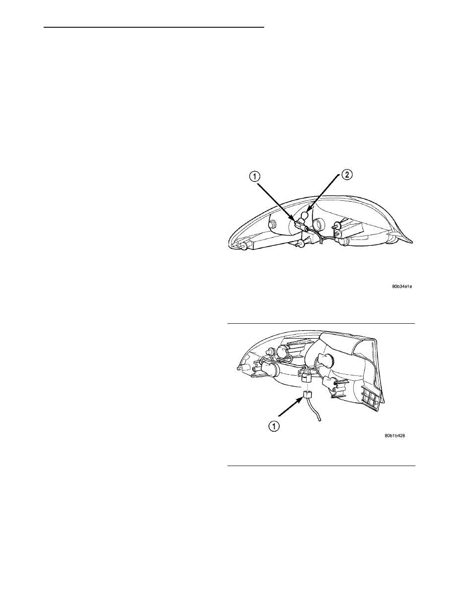
(5) Remove socket(s) from tail lamp unit (Fig. 58),
(Fig. 59), and (Fig. 60).
(6) Pull lamp from socket.
INSTALLATION
(1) Push lamp into socket.
(2) Install socket(s) in tail lamp unit.
(3) Place tail lamp unit in position on rear closure
panel.
(4) Install nuts attaching tail lamp unit to rear
closure panel.
(5) Install trunk lining.
Fig. 58 TAIL LAMP - CONCORDE
1 - SOCKET
2 - BULB
Fig. 59 TAIL LAMP - INTREPID
1 - BODY WIRE HARNESS CONNECTOR
LH
LAMPS/LIGHTING - EXTERIOR
8L - 43
SPOT LAMP ASSEMBLY - POLICE (Continued)
(6) Connect the battery negative cable and close
hood.
(7) Verify lamp operation.
TAIL LAMP UNIT
REMOVAL
(1) Release decklid latch and open decklid.
(2) Remove fasteners attaching trunk lining to
lower rear trunk panel.
(3) Move the trunk lining to access the tail lamp
unit fasteners.
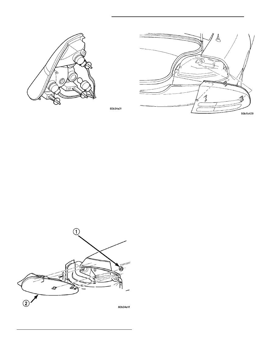
(4) Remove nuts attaching tail lamp unit to lower
trunk and quarter panel (Fig. 61), (Fig. 62) and (Fig.
60).
(5) Remove tail lamp unit from vehicle.
(6) Disconnect tail lamp unit wire connector from
body wire harness.
INSTALLATION
(1) Connect tail lamp unit wire connector to body
wire harness.
(2) Place tail lamp unit in position on vehicle.
(3) Install nuts to attach tail lamp unit to lower
trunk and quarter panel.
(4) Place trunk lining in position on lower trunk
panel.
(5) Install fasteners to attach trunk lining to lower
rear trunk panel.
(6) Verify lamp operation.
TURN SIGNAL LAMP UNIT -
CONCORDE/300M
REMOVAL
(1) Open hood, disconnect and isolate the battery
negative cable.
(2) Remove headlamp unit to access lamp housing.
(3) Rotate and pull socket from lamp unit.
(4) Disconnect fastener attaching lamp unit to fas-
cia (Fig. 63).
(5) Remove lamp unit from vehicle.
INSTALLATION
(1) Place lamp unit in position on fascia.
(2) Install lamp unit fastener.
(3) Install bulb socket in lamp unit.
(4) Connect the battery negative cable.
(5) Verify lamp operation.
(6) Install headlamp unit.
(7) Close hood.
Fig. 60 TAIL LAMP - 300M
Fig. 61 TAIL LAMP - CONCORDE
1 - PLASTIC HEX NUT (4)
2 - TAIL LAMP UNIT
Fig. 62 TAIL LAMP - INTREPID
8L - 44
LAMPS/LIGHTING - EXTERIOR
LH
TAIL LAMP (Continued)
Нет комментариевНе стесняйтесь поделиться с нами вашим ценным мнением.
Текст