Chrysler 300M, Dodge Interpid. Manual — part 92
300M
(1) Push bulb into socket (Fig. 44). Rotate socket.
(2) Reach under the fascia and place the socket
into the lamp housing and rotate to lock.
(3) Connect and the battery negative cable and
close hood.
CONCORDE
(1) Push bulb into lamp socket.
(2) Place lamp socket into headlamp housing and
rotate to the lock position.
(3) Connect wire connector to lamp socket(s).
(4) Verify headlamp operation.
(5) Install headlamp housing.
(6) Verify headlamp operation and alignment.
REAR FOG LAMP - EXPORT
DESCRIPTION
Some vehicles are equipped with rear fog lamps
(Fig. 45). The rear fog lamp is integrated into the tail
lamp assembly. If the rear fog lamp proves faulty the
entire tail lamp must be replaced. Rear fog lamps
utilize a red lens and clear bulb.
Rear fog lamps are standard equipment in certain
parts of the world where excessive fog is experienced
on a regular basis.
OPERATION
The rear fog lamps are turned ON and OFF with
the rear fog lamp switch. (Refer to 8 - ELECTRICAL/
LAMPS/LIGHTING
-
EXTERIOR/FOG
LAMP
SWITCH - OPERATION) and Wiring Diagrams.
DIAGNOSIS AND TESTING - REAR FOG LAMP
- EXPORT
NOTE: Battery must be completely charged (12v)
prior to testing. It may also be necessary to install
battery charger on the vehicles electrical system
when performing this test. Refer to the Battery sec-
tion of the service manual for detailed information.
(1) Remove the rear fog lamp bulb and check for
burned out condition, replace bulb if necessary.
(2) If bulb appears OK, reinstall the bulb in its
socket and turn fog lamps ON and check for proper
operation. If lamp is still inoperative proceed to Step
3.
(3) Remove lamp bulb and check for proper power
(12v) and ground connections in lamp socket. If
power and/or ground connections are not present,
trace wire until open or short is found.
REMOVAL
(1) Remove the tail lamp from the vehicle.
(2) Rotate the rear fog lamp socket one-third turn
and pull from lamp housing (Fig. 45).
(3) Pull the rear fog lamp bulb straight from its
socket.
INSTALLATION
(1) Install the rear fog lamp bulb and socket in the
lamp housing (Fig. 45).
(2) Verify lamp operation.
(3) Install the tail lamp assembly in the vehicle.
REAR FOG LAMP SWITCH -
EXPORT
DESCRIPTION
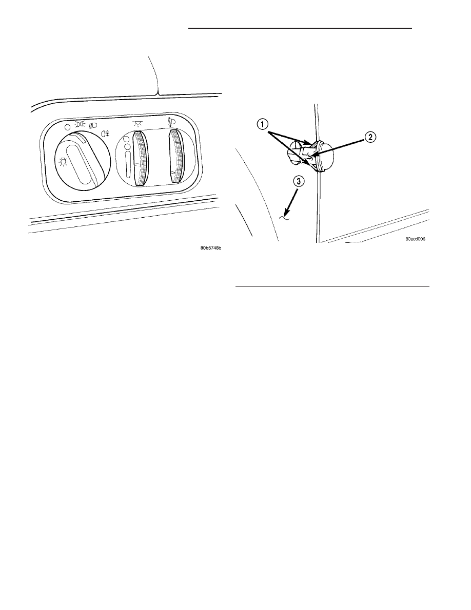
Vehicles equipped with rear fog lamps utilize a
rear fog lamp switch. This switch is located next to
the headlamp switch on (Fig. 46). The rear fog lamp
switch is the primary controller of the rear fog
lamps.
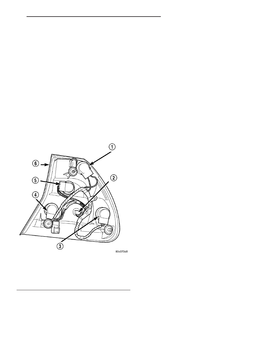
Fig. 45 TAIL LAMP BULBS
1 - REAR TURN SIGNAL LAMP
2 - REAR TAIL LAMP
3 - REAR STOP LAMP
4 - REAR FOG LAMP
5 - BACK-UP LAMP
6 - TAIL LAMP ASSEMBLY
LH
LAMPS/LIGHTING - EXTERIOR
8L - 37
PARK/TURN SIGNAL LAMP (Continued)
OPERATION
With the rotation of the rear fog lamp switch, volt-
age is sent through the rear fog lamp switch. This
illuminates the rear fog lamp or lamps. The head-
lamps must be “on” in order for the rear fog lamp/s to
function. Refer to the appropriate wiring information.
The wiring information includes wiring diagrams,
proper wire and connector repair procedures, details
of wire harness routing and retention, connector pin-
out information and location views for the various
wire harness connectors, splices and grounds.
REMOVAL
The rear fog lamp switch is integrated into the
headlamp switch on LH models. If the rear fog lamp
switch proves faulty the entire headlamp switch
must be replaced. (Refer to 8 - ELECTRICAL/
LAMPS/LIGHTING
-
EXTERIOR/HEADLAMP
SWITCH - REMOVAL).
INSTALLATION
The rear fog lamp switch is integrated into the
headlamp switch on LH models. If the rear fog lamp
switch proves faulty the entire headlamp switch
must be replaced. (Refer to 8 - ELECTRICAL/
LAMPS/LIGHTING
-
EXTERIOR/HEADLAMP
SWITCH - INSTALLATION).
SIDE REPEATER LAMP -
EXPORT
DESCRIPTION
One Side Repeater Lamp can be found on each side
of the vehicle just behind the front wheel (Fig. 47).
The side repeater lamp utilizes an amber colored
housing and clear bulb.
OPERATION
The side repeater lamps are turned ON or OFF
with the turn signal lamps. These lamps are con-
trolled by the steering column mounted multi-func-
tion switch.
DIAGNOSIS AND TESTING - SIDE REPEATER
LAMP - EXPORT
(1) Remove the suspect side repeater lamp bulb
and check for burned out condition. Replace bulb if
necessary.
(2) If the bulb appears to be OK, reinstall the bulb
in its socket and rotate the ignition switch to the ON
position. Turn the appropriate turn signal lamp ON
and check for lamp operation. If lamp is still inoper-
ative proceed to Step 3.
(3) Remove the suspect side repeater lamp bulb
and check for power (12v) and ground connections in
lamp socket. If either are not present, trace wire
until open or short is found.
REMOVAL
(1) Open front door.
Fig. 46 REAR FOG LAMP SWITCH
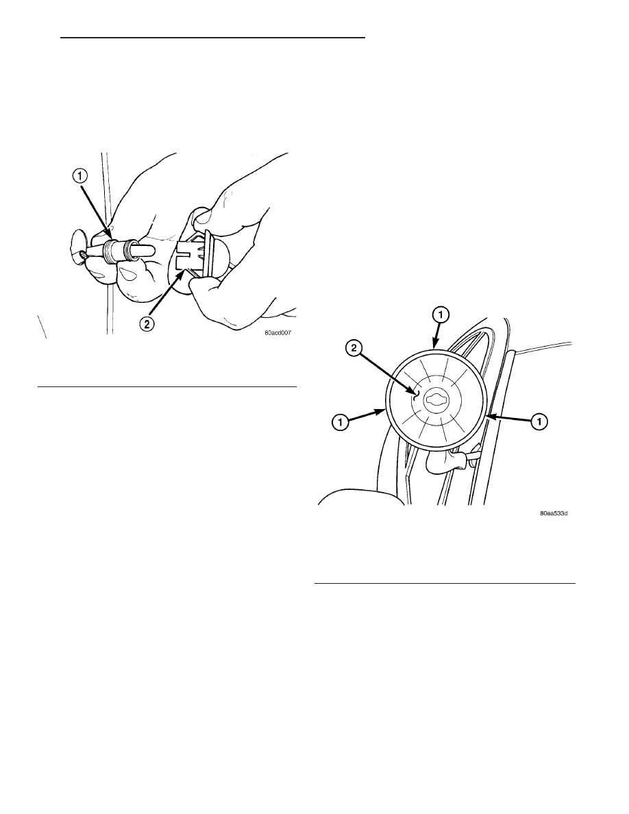
Fig. 47 SIDE REPEATER LAMP
1 - SIDE REPEATER LAMP RETAINING TABS
2 - SIDE REPEATER LAMP HOUSING
3 - FENDER
8L - 38
LAMPS/LIGHTING - EXTERIOR
LH
REAR FOG LAMP SWITCH - EXPORT (Continued)
(2) Reach up behind the side repeater lamp and
depress the two lamp unit retaining tabs. Remove
the lamp unit from the fender opening.
(3) Rotate the side repeater lamp unit counter-
clockwise and remove the lamp socket from the lamp
unit (Fig. 48).
(4) Pull the lamp bulb straight from its socket.
INSTALLATION
(1) Install the side repeater lamp bulb in the
socket.
(2) Verify lamp operation.
(3) Install the side repeater lamp socket into the
lamp unit.
(4) Install the side repeater lamp in the front
fender. Be certain lamp unit is secure in fender.
SIDE REPEATER LAMP UNIT -
EXPORT
REMOVAL
(1) Working in the appropriate front wheel well,
remove the rear most fasteners from the front wheel-
house liner.
(2) Reach up behind the side repeater lamp and
depress the two lamp housing retaining tabs (Fig.
48). Remove the side repeater lamp unit from the
fender opening.
(3) Rotate the side repeater lamp unit counter-
clockwise and remove the lamp socket from the lamp
unit (Fig. 48).
INSTALLATION
(1) Install the side repeater lamp socket into the
lamp unit.
(2) Install the side repeater lamp in the front
fender (Fig. 48). Be certain lamp is secure within the
fender.
(3) Install the front wheelhouse liner.
(4) Verify lamp operation.
SPOT LAMP - POLICE
REMOVAL
(1) Remove the PDC cover and pull either the X or
Y fuse, depending on which spot lamp is being ser-
viced.
(2) Raise the spot lamp from the stowed to the
operating position.
(3) Support the spot lamp sealed beam in position.
(4) Remove the screws retaining the bezel to the
spot lamp head assembly (Fig. 49).
(5) Remove the bezel from the spot lamp head
assembly.
(6) Tilt the sealed beam away from the spot lamp
head assembly.
(7) Disconnect the electrical connector to the spot
lamp head assembly.
(8) Remove the bulb from the lamp housing by
moving the hold downs.
(9) Remove bulb from lamp.
INSTALLATION
(1) Position bulb into spot lamp assembly.
(2) Install the hold downs.
Fig. 48 SIDE REPEATER LAMP/HOUSING
1 - BULB SOCKET
2 - SIDE REPEATER LAMP UNIT
Fig. 49 SPOT LAMP RETAINING SCREWS -
REMOVE/INSTALL
1 - SPOT LAMP HEAD ASSEMBLY BEZEL RETAINING SCREWS
2 - SPOT LAMP
LH
LAMPS/LIGHTING - EXTERIOR
8L - 39
SIDE REPEATER LAMP - EXPORT (Continued)
(3) Connect the electrical connector to the spot
lamp head assembly.
(4) Tilt the sealed beam toward the spot lamp
head assembly.
(5) Install the bezel to the spot lamp head assem-
bly.
(6) Install the screws retaining the bezel to the
spot lamp head assembly (Fig. 49) and tighten to 2
N·m (18 in. lbs.).
(7) Lower the spot lamp from the operating to
stowed position.
(8) Install the fuse and PDC cover.
(9) Verify system and vehicle operation.
SPOT LAMP ASSEMBLY -
POLICE
DESCRIPTION
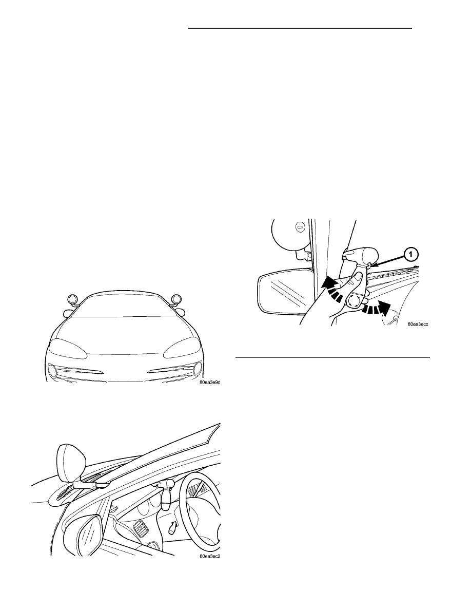
This vehicle may be equipped with up to two spot
lamp assemblies, attached to the A-Pillars (Fig. 50).
The spot lamp assembly switch is located on the han-
dle (Fig. 51), just above the rotating handle grip.
Each spot lamp assembly contains a 100 watt halo-
gen bulb. The spot lamp assemblies are fused indi-
vidually and powered hot at all times. There are
three fuses in the Power Distribution Center (PDC)
that control the spot lamp assemblies:
• Fuse F - IP ACC3/SPOT LPS - 50 amp
• Fuse X - SPOT LP LT - 20 amp
• Fuse Y - SPOT LP RT/UNDERHOOD - 20 amp
The parts available for service are:
• Complete spot lamp assembly.
• H3 100 watt halogen bulb.
• Inside control handle w/switch.
OPERATION
Use this switch to turn the spot lamp assembly ON
and OFF. Rotate and twist the handle to adjust the
position of the spot lamp assembly (Fig. 52).
DIAGNOSIS AND TESTING - SPOT LAMP
ASSEMBLY - POLICE
IF SPOT LAMP DOES NOT LIGHT
(1) If both spot lamps are inoperative, check fuse F
(spot lamp master). Refer to Wiring Diagrams for
fuse locations. If fuses are OK, refer to Step 4. If
fuse(s) are faulty, replace as necessary.
(2) If the left spot lamp is inoperative, check fuse
X. If fuse is OK, refer to Step 4. If fuse is faulty,
replace as necessary. If fuse blows again, find short
to ground. Refer to Wiring Diagrams for circuit infor-
mation.
(3) If the right spot lamp is inoperative, check fuse
Y. If fuse is OK, refer to Step 4. If fuse is faulty,
replace as necessary. If fuse blows again, find short
to ground. Refer to Wiring Diagrams for circuit infor-
mation.
Fig. 50 SPOT LAMP ASSEMBLY LOCATION
Fig. 51 SPOT LAMP ASSEMBLY
Fig. 52 SPOT LAMP ASSEMBLY OPERATION
1 - ON/OFF SWITCH
8L - 40
LAMPS/LIGHTING - EXTERIOR
LH
SPOT LAMP - POLICE (Continued)
Нет комментариевНе стесняйтесь поделиться с нами вашим ценным мнением.
Текст