
Chrysler Stratus Convertible. Manual — part 389
SPARK PLUG TUBE SEALS
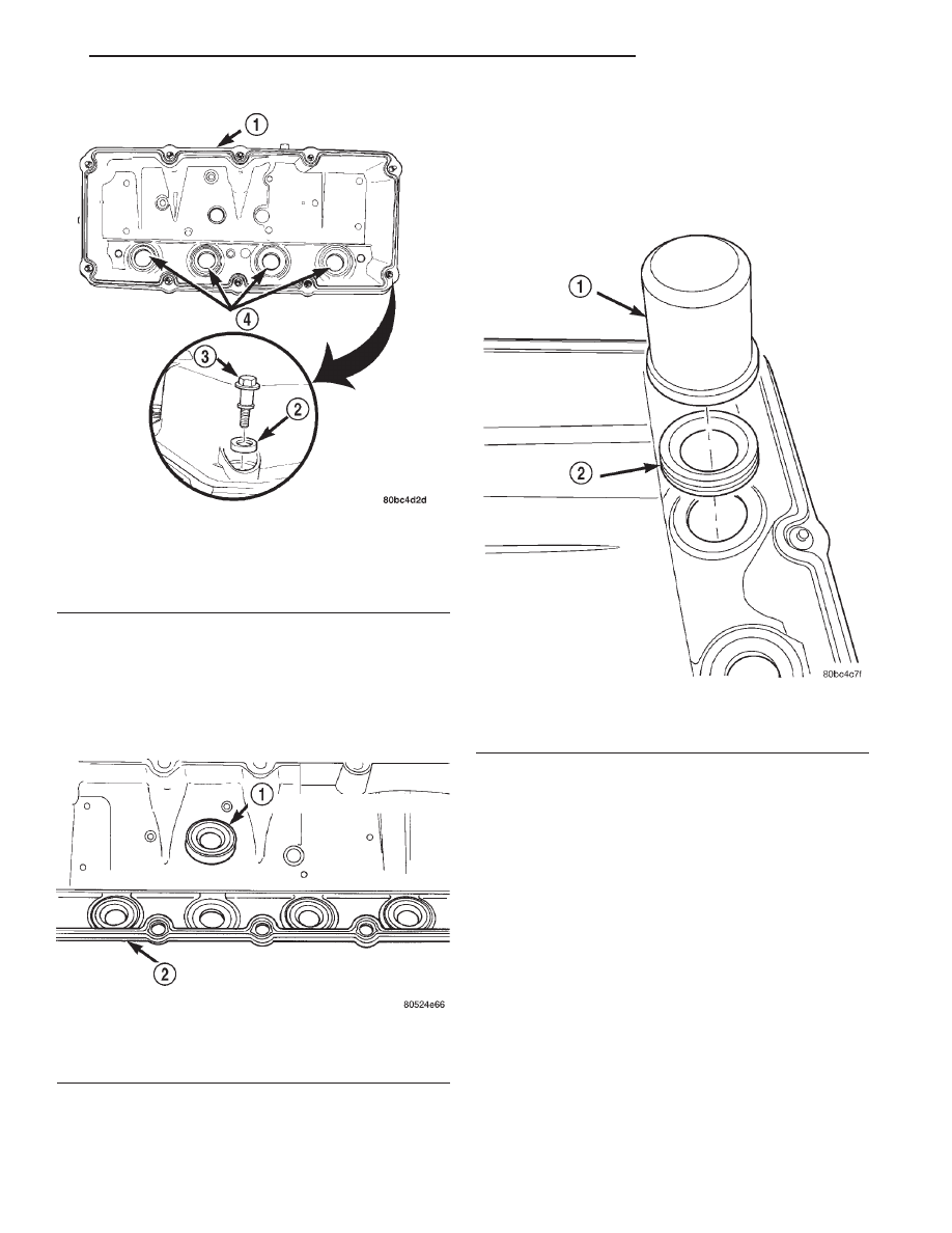
The spark plug tube seals are located in the cylin-
der head cover (Fig. 44). These seals are pressed into
the cylinder head cover to seal the outside perimeter
of the spark plug tubes. If these seals show signs of
hardness and/or cracking, they should be replaced.
REMOVAL
(1) Remove cylinder head. Refer to procedure in
this section.
(2) Using an appropriate tool, carefully remove
spark plug tube seals. Care should be taken not to
damage cylinder head cover sealing surfaces.
INSTALLATION
(1) Clean all sealing surfaces.
NOTE: Position seal with the concave side facing
the installation tool.
(2) Install seals using Special Tool MB-998306.
Only hand pressure on tool is needed to install new
seals.
(3) Install cylinder head cover. Refer to procedures
in this section.
SPARK PLUG TUBE
(1) Remove cylinder head cover. Refer to procedure
in this section.
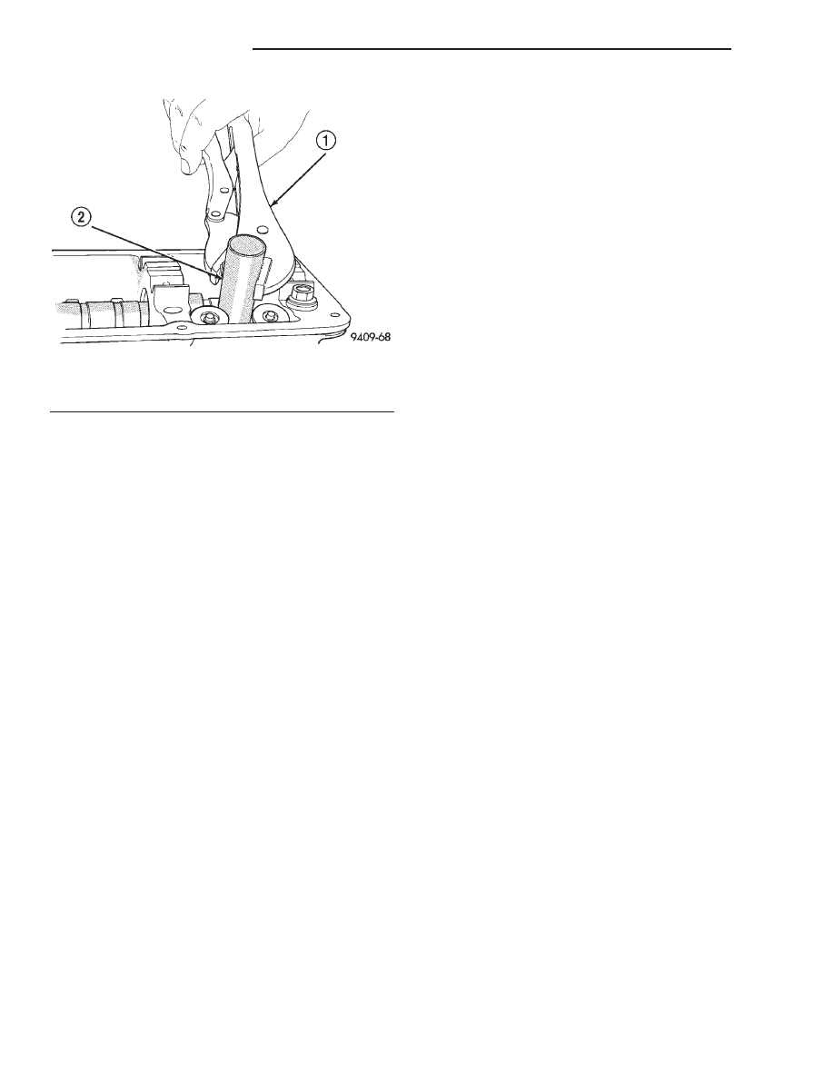
(2) Using locking pliers remove the tube from the
cylinder head (Fig. 46). Discard old tube.
Fig. 43 Cylinder Head Cover Gasket and Seals
1 – CYLINDER HEAD COVER GASKET
2 – SEAL
3 – BOLT
4 – SPARK PLUG TUBE SEALS
Fig. 44 Spark Plug Tube Seals
1 – SPARK PLUG TUBE SEAL
2 – CYLINDER HEAD COVER
Fig. 45 Spark Plug Tube Seal Installation
1 – SPECIAL TOOL MB-998306
2 – SPARK PLUG TUBE SEAL
JX
2.0L SOHC ENGINE
9 - 29
REMOVAL AND INSTALLATION (Continued)
(3) Clean area around spark plug with Mopar
t
parts cleaner or equivalent.
(4) Apply Mopar
t Stud and Bearing Mount or
equivalent to a new tube approximately 1 mm from
the end in a 3 mm wide area.
(5) Install sealer end of tube into the cylinder
head. Then carefully install the tube using a hard-
wood block and mallet until the tube is seated into
the bottom of the bore.
(6) Install cylinder head cover. Refer to procedure
in this section.
CAMSHAFT
NOTE: TO REMOVE CAMSHAFT, THE CYLINDER
HEAD MUST BE REMOVED.
REMOVAL
(1) Perform fuel system pressure release procedure
before attempting any repairs. Refer to Group 14,
Fuel System
(2) Remove the cylinder head cover. Refer to proce-
dure in this section.
(3) Mark rocker arm shaft assemblies so that they
are installed in their original positions.
(4) Remove rocker arm shaft bolts. Refer to proce-
dure in this section.
(5) Remove timing belt, timing belt tensioner, and
camshaft sprocket. Refer to procedures in this section.
(6) Remove rear timing belt cover.
(7) Remove cylinder head. Refer to procedure in
this section.
(8) Remove camshaft sensor and camshaft target
magnet.
(9) Remove camshaft from the rear of cylinder
head.
INSPECT CYLINDER HEAD FOR THE FOLLOWING:
NOTE:
•
Check oil feed holes for blockage.
•
Inspect cylinder head camshaft bearings for
wear, Refer to Cylinder Head, Inspection and Clean-
ing.
•
Check camshaft bearing journals for scratches
and worn areas. If light scratches are present, they
may be removed with 400 grit sand paper. If deep
scratches are present, replace the camshaft and
check the cylinder head for damage. Replace the
cylinder head if worn or damaged. Check the lobes
for pitting and wear. If the lobes show signs of
wear, check the corresponding rocker arm roller for
wear or damage. Replace rocker arm/hydraulic lash
adjuster if worn or damaged. If lobes show signs of
pitting on the nose, flank or base circle; replace the
camshaft.
INSTALLATION
(1) Lubricate the camshaft journals with oil and
install camshaft without rocker arm assemblies
installed.
(2) Install camshaft target magnet into the end of
the camshaft. Tighten mounting screw to 3.4 N·m (30
in. lbs.).
(3) Install camshaft position sensor and tighten
mounting screws to 9 N·m (80 in. lbs.).
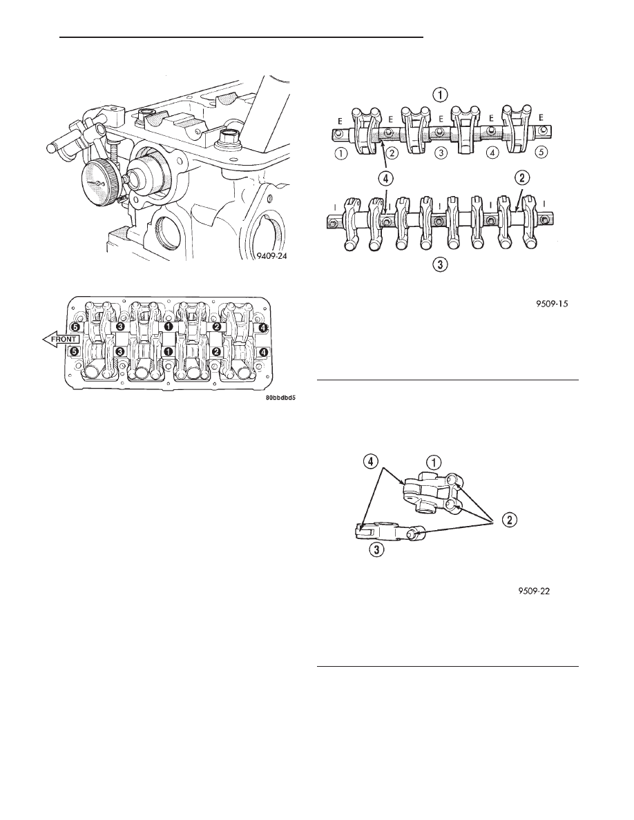
(4) Measure camshaft end play using the following
procedure:
• Mount dial indicator C-3339 or equivalent, to a
stationary point on cylinder head (Fig. 47).
• Using a suitable tool, move camshaft to rear-
ward limits of travel.
• Zero the dial indicator.
• Move camshaft forward to limits of travel and
read dial indicator.
• End play travel: 0.13 - 0.33 mm (0.005 - 0.013
in.).
(5) Install front camshaft seal. Camshaft must be
installed before the camshaft seal is installed. Refer
to procedure in this section.
(6) Install cylinder head. Refer to procedure in this
section.
(7) Install camshaft sprocket and tighten to 115
N·m (85 ft. lbs.).
(8) Install rear timing belt cover.
(9) Install timing belt tensioner and timing belt.
Refer to procedures in this section.
(10) Install rocker arm assemblies in correct order
as removed. Tighten the rocker arm assemblies in
sequence shown in (Fig. 48) to 28 N·m (250 in. lbs.).
Fig. 46 Spark Plug Tube—Removal
1 – LOCKING PLIERS
2 – SPARK PLUG TUBE
9 - 30
2.0L SOHC ENGINE
JX
REMOVAL AND INSTALLATION (Continued)
(11) Install cylinder head cover and tighten fasten-
ers to 12 N·m (105 in. lbs.).
(12) Install ignition coil and ignition cables.
ROCKER ARM/HYDRAULIC LASH ADJUSTER
REMOVAL
(1) Remove cylinder head cover using procedure in
this section.
(2) Identify the rocker arm shaft assemblies before
removal.
(3) Loosen the attaching fasteners. Remove rocker
arm shaft assemblies from cylinder head.
(4) Identify the rocker arms spacers and retainers
for reassembly. Disassemble the rocker arm assem-
blies by removing the attaching bolts from the shaft
(Fig. 49).
(5) Slide the rocker arms and spacers off the shaft.
Keep the spacers and rocker arms in the same loca-
tion for reassembly.
NOTE: Inspect the rocker arm for scoring, wear on
the roller or damage to the rocker arm (Fig. 50)
Replace if necessary. Check the location where the
rocker arms mount to the shafts for wear or dam-
age. Replace if damaged or worn. The rocker arm
shaft is hollow and is used as a lubrication oil duct.
Check oil holes for clogging with small wire, clean
as required. Lubricate the rocker arms and spacers.
Install onto shafts in their original position (Fig. 49).
INSTALLATION
CAUTION: Set crankshaft to 3 notches before TDC
before installing rocker arm shafts. Refer to Timing
Belt System and Camshaft Seal Service of this sec-
tion for procedure.
Fig. 47 Camshaft End Play
Fig. 48 Rocker Arm Shaft Tightening Sequence
Fig. 49 Rocker Arm Shaft Assemblies
1 – EXHAUST ROCKER ARM ASSEMBLY
2 – PLASTIC SHAFT SPACERS
3 – INTAKE ROCKER ARM ASSEMBLY
4 – ROCKER ARM SHAFT RETAINERS
Fig. 50 Rocker Arm Assemblies
1 – EXHAUST ROCKER ARM
2 – HYDRAULIC LASH ADJUSTERS
3 – INTAKE ROCKER ARM
4 – ROLLERS
JX
2.0L SOHC ENGINE
9 - 31
REMOVAL AND INSTALLATION (Continued)
(1) Install
rocker
arm/hydraulic
lash
adjuster
assembly making sure that adjusters are at least
partially full of oil. This is indicated by little or no
plunger travel when the lash adjuster is depressed. If
there is excessive plunger travel. Place the rocker
arm assembly into clean engine oil and pump the
plunger until the lash adjuster travel is taken up. If
travel is not reduced, replace the assembly. Hydraulic
lash adjuster and rocker arm are serviced as an
assembly.
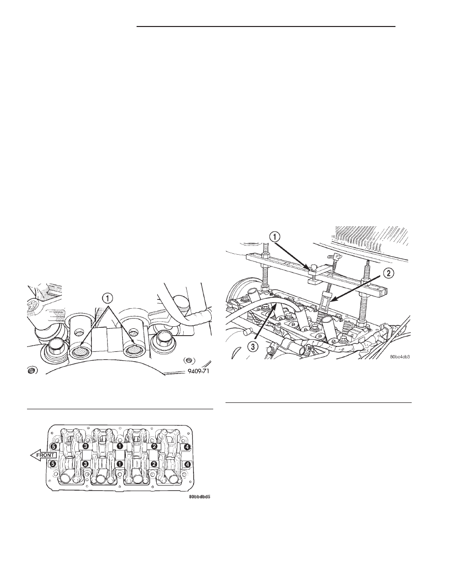
(2) Install rocker arm and shaft assemblies with
NOTCH in the rocker arm shafts pointing up and
toward the timing belt side of the engine (Fig. 51).
Install the retainers in their original positions on the
exhaust and intake shafts (Fig. 49).
CAUTION: When installing the intake rocker arm
shaft assembly be sure that the plastic spacers do
not interfere with the spark plug tubes. If the spac-
ers do interfere rotate until they are at the proper
angle. To avoid damaging the spark plug tubes, do
not attempt rotating the spacers by forcing down
the shaft assembly.
(3) Tighten bolts to 28 N·m (250 in. lbs.) in
sequence shown in (Fig. 52).
HYDRAULIC LASH ADJUSTER NOISE
A tappet-like noise may be produced from several
items. Refer to Lash Adjuster Noise - Diagnosis in
Standard Service Procedures, in this Group. Lash
adjusters are replaced with the rocker arm as
an assembly.
VALVE SEAL AND SPRING—IN VEHICLE
REMOVAL
(1) Remove rocker arm shafts assemblies. Refer to
procedure in this section.
(2) Rotate crankshaft until piston is at TDC on
compression stroke.
(3) With air hose attached to adapter tool installed
in spark plug hole, apply 90-120 psi air pressure.
(4) Using Special Tool MD-998772A with adapter
6779 (Fig. 53) compress valve springs and remove
valve locks.
(5) Remove valve spring.
(6) Remove valve stem seal by using a valve stem
seal tool (Fig. 54).
Fig. 51 Rocker Arm Shaft Notches
1 – NOTCHES FACING UP AND TOWARD THE TIMING BELT
SIDE OF THE ENGINE
Fig. 52 Rocker Arm Shaft Tightening Sequence
Fig. 53 Valve Spring—Removing and Installing
1 – VALVE SPRING COMPRESSOR SPECIAL TOOL MD-998772A
2 – ADAPTER 6779
3 – AIR HOSE
9 - 32
2.0L SOHC ENGINE
JX
REMOVAL AND INSTALLATION (Continued)
Нет комментариевНе стесняйтесь поделиться с нами вашим ценным мнением.
Текст