
Chrysler Stratus Convertible. Manual — part 390
INSTALLATION
(1) Install valve seal/valve spring seat assembly.
Refer to Valve Installation procedure in this section.
(2) Using Special Tool MD-998772A compress valve
springs only enough to install locks. Correct align-
ment of tool is necessary to avoid nicking valve stems
(air pressure required), piston at TDC.
(3) Install rocker arm shaft assemblies. Refer to
procedure in this section.
(4) Install cylinder head cover. Refer to procedure
in this section.
CYLINDER HEAD
REMOVAL
(1) Perform fuel system pressure release procedure
before attempting any repairs. Refer to Group 14,
Fuel System.
(2) Disconnect battery negative cable from auxil-
iary jumper terminal.
(3) Drain cooling system. Refer to Group 7, Cooling
System.
(4) Remove air cleaner inlet duct and air cleaner
upper housing, disconnect all vacuum lines, electrical
wiring and fuel lines from throttle body.
(5) Remove throttle linkage.
(6) Remove accessory drive belts. Refer to Group 7,
Cooling System for procedure.
(7) Remove power brake vacuum hose from intake
manifold.
(8) Raise vehicle and remove exhaust pipe from
manifold.
(9) Remove power steering fluid reservoir and set
aside.
(10) Disconnect ignition coil wiring connector and
remove ignition coil from engine.
(11) Remove cylinder head cover. Refer to proce-
dure in this section.
(12) Remove cam sensor and fuel injectors wiring
connectors.
(13) Remove intake manifold. Refer to procedure
in this section.
(14) Remove timing belt, camshaft sprocket and
rear timing belt cover. Refer to procedures in this
section.
(15) Remove rocker arm shaft assemblies.
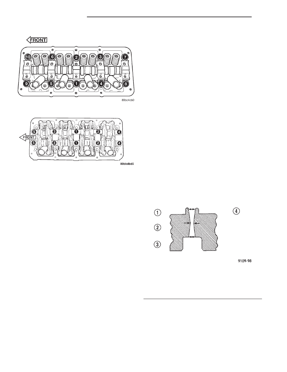
(16) Remove cylinder head bolts in reverse order of
tightening sequence (Fig. 60).
(17) Carefully lift cylinder head from block.
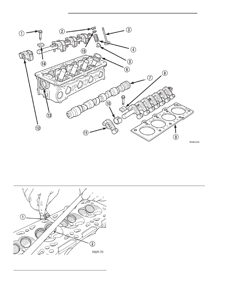
NOTE: Inspect camshaft bearing journals for scor-
ing. Cylinder head must be flat within 0.1 mm (0.004
inch) (Fig. 56).
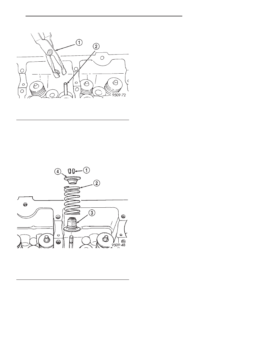
Fig. 54 Valve Stem Oil Seal Tool
1 – VALVE SEAL TOOL
2 – VALVE STEM
Fig. 55 Valve Spring Assembly
1 – VALVE RETAINING LOCKS
2 – VALVE SPRING
3 – VALVE SEAL AND VALVE SPRING SEAT ASSEMBLY
4 – VALVE SPRING RETAINER
JX
2.0L SOHC ENGINE
9 - 33
REMOVAL AND INSTALLATION (Continued)
INSTALLATION
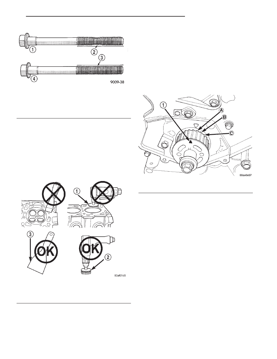
EXAMINING CYLINDER HEAD BOLTS
NOTE: The cylinder head bolts should be examined
BEFORE reuse. If the threads are necked down, the
bolts should be replaced (Fig. 57).
Necking can be checked by holding a scale or
straight edge against the threads. If all the threads
do not contact the scale, the bolt(s) should be
replaced.
Cylinder Head and Valve Assembly
1 – ROCKER SHAFT RETAINING BOLT
2 – VALVE RETAINING LOCKS
3 – VALVE
4 – VALVE SPRING
5 – VALVE SEAL AND VALVE SPRING SEAT ASSEMBLY
6 – SPARK PLUG TUBE SEAL
7 – CAMSHAFT
8 – ROCKER ARM SHAFT RETAINER SPACER
9 – GASKET
10 – SPACER
11 – INTAKE ROCKER ARM/HYDRAULIC LASH ADJUSTER
ASSEMBLY
12 – EXHAUST ROCKER ARM/HYDRAULIC LASH ADJUSTER
ASSEMBLY
13 – CAMSHAFT SEAL
14 – RETAINER SPACER
15 – VALVE SPRING RETAINER
Fig. 56 Checking Cylinder Head Flatness
1 – FEELER GAUGE
2 – STRAIGHT EDGE
9 - 34
2.0L SOHC ENGINE
JX
REMOVAL AND INSTALLATION (Continued)
CLEANING CYLINDER HEAD SEALING SURFACES
CAUTION: When cleaning cylinder head and cylin-
der block surfaces, DO NOT use a metal scraper.
Sealing surfaces could be cut or ground, resulting
in gasket leaks. Use only the cleaning methods
shown in (Fig. 58). If required, use a white (120 grit)
3M Roloc
Y
bristle disk on aluminum surfaces. A
yellow (80 grit) bristle disk can be used on cast iron
surfaces with care.
(1) Clean the cylinder head and cylinder block
sealing surfaces using a wood/plastic scraper. Apply
solvent or a commercially available gasket remover
to help soften the gasket residue. If additional clean-
ing is required, use a white (120 grit) 3M Roloc
y
bristle disk and a drill motor to remove gasket resi-
due.
(2) Apply Mopar
t Gasket Sealant (aerosol can) to
both sides of the new cylinder head gasket.
(3) Position a new cylinder head gasket on the
locating dowels.
(4) Position crankshaft sprocket to TDC, then
rotate crankshaft until mark is three teeth before
TDC (Fig. 59). This will ensure that no piston-to-
valve contact occurs upon installation of cylinder
head in the event of camshaft rotation.
(5) Position the cylinder head onto the cylinder
block. Make sure the cylinder head seats fully over
the locating dowels.
(6) Before installing the cylinder head bolts, the
threads should be oiled with engine oil. The 4 short
bolts 110 mm (4.330 in.) are to be installed in posi-
tions 7, 8, 9, and 10 (Fig. 60).
(7) Tighten the cylinder head bolts in the sequence
shown in (Fig. 60). Using the 4 step torque method,
tighten according to the following values:
• First All to 34 N·m (25 ft. lbs.)
• Second All to 68 N·m (50 ft. lbs.)
• Third All to 68 N·m (50 ft. lbs.)
• Fourth Turn an additional 1/4 Turn, Do not use
a torque wrench for this step.
(8) Install rocker shaft assemblies in correct order
as removed. Tighten rocker arm shaft bolts in
sequence shown in (Fig. 61) to 28 N·m (250 in. lbs.).
(9) Install
rear
timing
belt
cover,
camshaft
sprocket, and timing belt. Refer to procedures in this
section.
(10) Install intake manifold. Refer to procedure in
this section.
(11) Connect electrical connectors to cam sensor
and fuel injectors.
Fig. 57 Checking Bolts for Stretching (Necking)
1 – STRETCHED BOLT
2 – THREADS ARE NOT STRAIGHT ON LINE
3 – THREADS ARE STRAIGHT ON LINE
4 – UNSTRETCHED BOLT
Fig. 58 Proper Tool Usage for Surface Preparation
1 – ABRASIVE PAD
2 – 3M ROLOC
Y
BRISTLE DISC
3 – PLASTIC/WOOD SCRAPER
Fig. 59 Crankshaft Sprocket Position
1 – TDC MARK
JX
2.0L SOHC ENGINE
9 - 35
REMOVAL AND INSTALLATION (Continued)
(12) Install cylinder head cover and tighten fasten-
ers to 12 N·m (105 in. lbs.).
(13) Connect PCV and make-up air hose to cylin-
der head cover.
(14) Install power steering reservoir.
(15) Install ignition coil and connect wiring con-
nector.
(16) Connect power brake booster vacuum hose to
intake manifold.
(17) Connect throttle linkage to throttle body.
(18) Connect all vacuum lines and electrical wiring
connectors.
(19) Install air cleaner inlet duct and upper air
cleaner housing.
(20) Raise vehicle on hoist and connect exhaust
system to exhaust manifold.
(21) Lower vehicle and connect negative cable to
auxiliary battery terminal.
(22) With the DRB scan tool use ASD Fuel System
Test to pressurize fuel system. Check for fuel leaks.
CAUTION: When using the ASD Fuel System Test,
the Auto Shutdown (ASD) relay will remain ener-
gized for 7 minutes or until the ignition switch is
turned to the OFF position, or Stop All Test is
selected.
VALVE SERVICE WITH THE CYLINDER HEAD
REMOVED
REMOVAL
(1) With cylinder head removed, compress valve
springs using Special Tool C-3422-B with Adaptor
6526.
(2) Remove valve retaining locks, valve spring
retainers, valve stem seals and valve springs.
(3) Before removing valves, remove any burrs
from valve stem lock grooves to prevent dam-
age to the valve guides. Identify valves to insure
installation in original location.
VALVE INSPECTION
(1) Clean valves thoroughly and discard burned,
warped and cracked valves.
(2) Measure valve stems for wear. Measure stem
about 60 mm beneath the valve lock grooves.
(3) If valve stems are worn more than 0.05 mm
(0.002 in.), replace valve.
VALVE GUIDES
(1) Remove carbon and varnish deposits from
inside of valve guides with a reliable guide cleaner.
(2) Using a small hole gauge and a micrometer,
measure valve guides in 3 places top, middle and bot-
tom (Fig. 62). Replace guides if they are not within
specification. For specifications, refer to Engine Spec-
ifications in this section.
(3) Check valve guide height (Fig. 63).
Fig. 60 Cylinder Head Tightening Sequence
Fig. 61 Rocker arm Tightening Sequence
Fig. 62 Checking Wear on Valve Guide—Typical
1 – TOP
2 – MIDDLE
3 – BOTTOM
4 – CUT AWAY VIEW OF VALVE GUIDE MEASUREMENT
LOCATIONS
9 - 36
2.0L SOHC ENGINE
JX
REMOVAL AND INSTALLATION (Continued)
Нет комментариевНе стесняйтесь поделиться с нами вашим ценным мнением.
Текст