
Chrysler Stratus Convertible. Manual — part 387
REAR MOUNT
(1) Raise vehicle on hoist.
(2) Remove through bolt from rear engine mount
and bracket (Fig. 26).
(3) Remove rear strut bracket and support bracket
(Fig. 23).
(4) Remove bending strut from rear mount to
engine (Fig. 24).
(5) Remove bolts attaching rear mount to suspen-
sion crossmember.
NOTE: It may be necessary to tilt engine for rear
mount removal clearance.
(6) Remove rear mount.
INSTALLATION
FRONT MOUNT
(1) Position front mount. Position damper weight
(some models) and install front mount to lower radi-
ator support attaching bolts. Tighten bolts to 61 N·m
(45 ft. lbs.).
(2) Install through bolt and tighten to 61 N·m (45
ft. lbs.) (Fig. 25).
(3) Lower vehicle.
REAR MOUNT
(1) Position rear mount.
(2) Install bolts attaching rear mount to front sus-
pension crossmember. Tighten bolts to 61 N·m (45 ft.
lbs.).
(3) Install rear strut and support brackets (Fig.
23). Tighten bolts to the following torque values:
• Bolts attaching strut bracket to front suspension
crossmember: 61 N·m (45 ft. lbs.)
• Nut attaching support bracket to front suspen-
sion crossmember: 108 N·m (80 ft. lbs.)
• Bolt attaching support bracket to rear strut: 61
N·m (45 ft. lbs.)
(4) Install through bolt and tighten to 61 N·m (45
ft. lbs.) (Fig. 26).
(5) Lower vehicle.
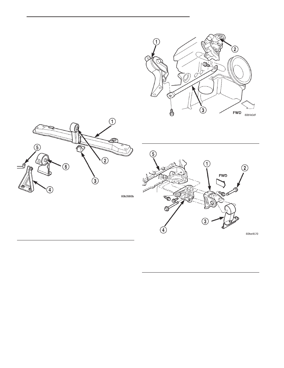
Fig. 23 Engine Mounting—Front and Rear
1 – LOWER RADIATOR SUPPORT
2 – FRONT ENGINE MOUNT
3 – DAMPER WEIGHT (SOME MODELS)
4 – REAR STRUT BRACKET
5 – SUPPORT BRACKET (SOME MODELS)
6 – REAR ENGINE MOUNT
Fig. 24 Bending Strut—Rear
1 – REAR MOUNT
2 – POWER STEERING PUMP
3 – BENDING STRUT
Fig. 25 Engine Mounting—Front
1 – FRONT TORQUE BRACKET
2 – THROUGH BOLT
3 – FRONT MOUNT
4 – STRUT
5 – ENGINE
JX
2.0L SOHC ENGINE
9 - 21
REMOVAL AND INSTALLATION (Continued)
ENGINE MOUNT AND SUPPORT BRACKET—
RIGHT
NOTE: The right side engine mount is a Hydro-
Mount and may show surface cracks. This will not
effect
mount
performance
and
should
not
be
replaced. Replace the Hydro-Mount if fluid is leak-
ing from mount.
REMOVAL
(1) Raise vehicle on a hoist and remove inner
splash shield.
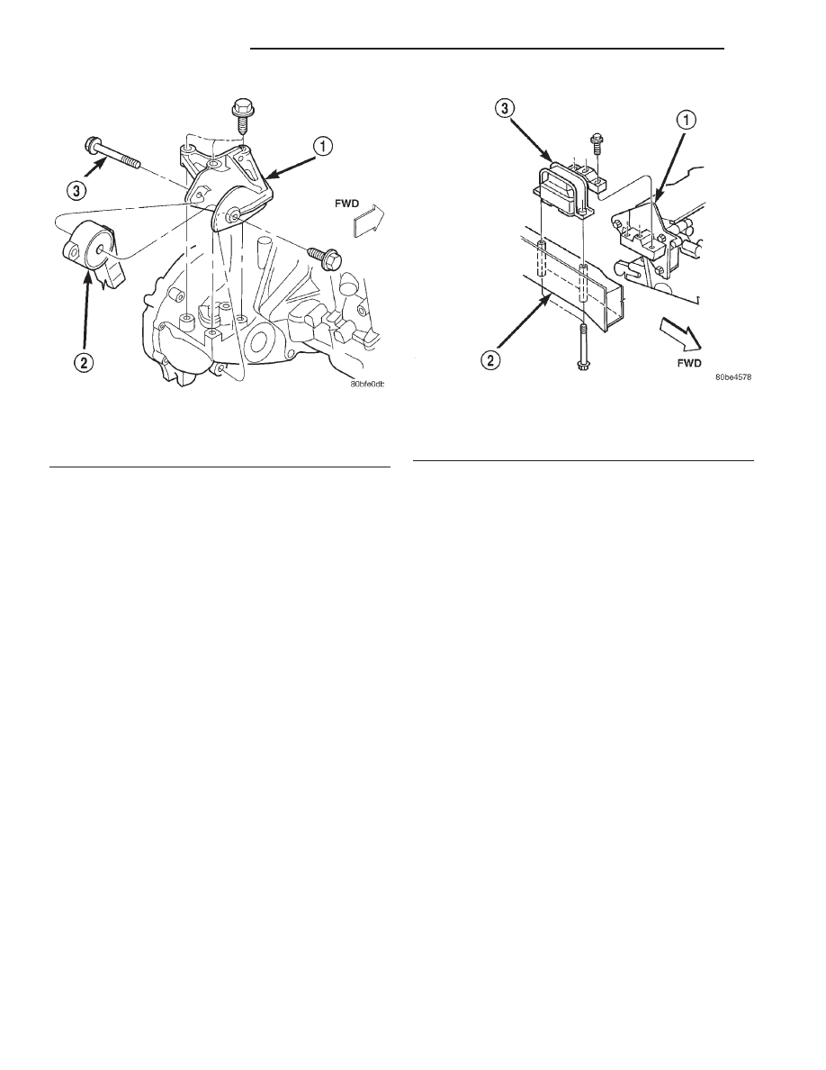
(2) Remove the right engine support assembly ver-
tical fasteners from frame rail (Fig. 27).
(3) Lower vehicle. Remove the load on the engine
motor mounts by carefully supporting the engine
assembly with a floor jack.
(4) Remove the three bolts attaching the engine
support assembly to the engine bracket.
(5) Move the air conditioning receiver/drier aside.
(6) Remove
coolant
reserve/recovery
container.
Refer to COOLING SYSTEM for procedure.
(7) Remove right engine mount.
(8) Remove the three bolts attaching the engine
support bracket to the cylinder block.
INSTALLATION
(1) Install engine support bracket (if removed).
Tighten bolts to 33 N·m (24 ft. lbs.).
(2) Position right engine mount and install frame
rail to mount bolts. Tighten bolts to 61 N·m (45 ft.
lbs.).
(3) Install the mount to engine bracket bolts and
tighten to 61 N·m (45 ft. lbs.).
(4) Install coolant reserve/recovery container. Refer
to COOLING SYSTEM for procedure.
(5) Position the air conditioning receiver/drier and
install mounting screw.
(6) Install inner splash shield.
NOTE: If centering or adjusting the engine/trans-
mission assembly is needed refer to Adjustments,
in this section.
ENGINE MOUNT—LEFT
NOTE: If centering or adjusting the engine/trans-
mission assembly is needed refer to Adjustments,
in this section.
The left side engine mount is a Hydro-Mount and
may show surface cracks. This will not effect it’s
performance and should not be replaced. Only
replace the Hydro-Mount when it’s leaking fluid.
REMOVAL
(1) Support the transmission with a transmission
jack.
(2) Remove the three vertical bolts (A) from the
mount to the transmission bracket (Fig. 28).
Fig. 26 Engine Mounting—Rear
1 – REAR TORQUE BRACKET
2 – REAR MOUNT
3 – THROUGH BOLT
Fig. 27 Engine Mounting—Right Side
1 – ENGINE SUPPORT BRACKET
2 – FRAME RAIL
3 – RIGHT ENGINE MOUNT
9 - 22
2.0L SOHC ENGINE
JX
REMOVAL AND INSTALLATION (Continued)
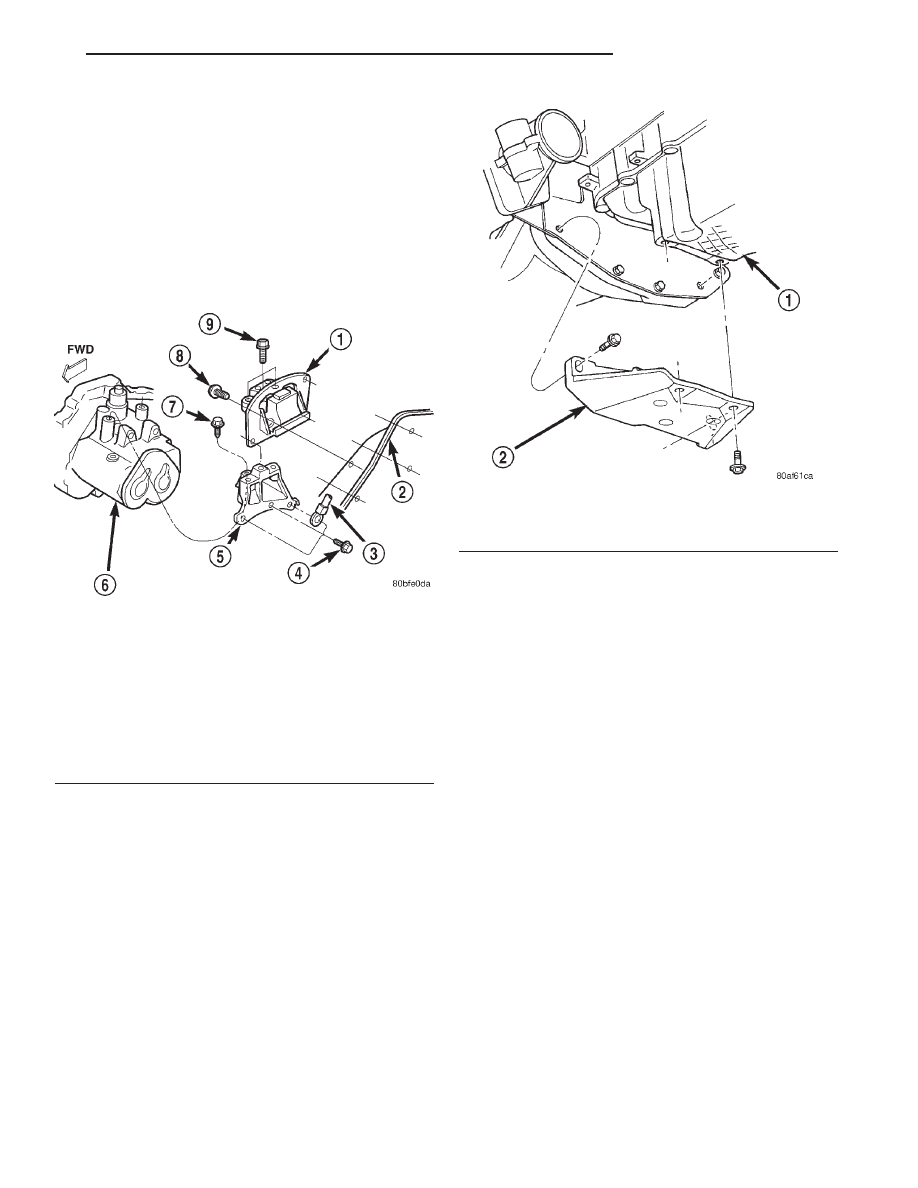
(3) Remove the mount to frame rail fasteners (B)
and remove mount (Fig. 28).
INSTALLATION
(1) Install mount. Tighten mount to frame rail fas-
teners (B) to 33 N·m (24 ft. lbs.) (Fig. 28).
(2) If removed, install transmission bracket and
tighten bolts (C) and (D) to 61 N·m (45 ft. lbs.) (Fig.
28).
(3) Install mount to transmission bracket vertical
bolts (A). Tighten to 61 N·m (45 ft. lbs.) (Fig. 28).
STRUCTURAL COLLAR
REMOVAL
(1) Raise vehicle on hoist.
NOTE: To remove transaxle dust cover, the front
bending strut must be removed.
(2) Remove structural collar from oil pan to tran-
saxle (Fig. 29).
INSTALLATION
CAUTION: The torque procedure for the structural
collar must be followed, as damage to oil pan or
collar could occur.
(1) Install the structural collar (Fig. 29) using the
following 3 step torque sequence:
• Step 1: Install the collar to oil pan bolts and
tighten to 3 N·m (30 in. lbs.).
• Step 2: Install collar to transaxle bolts and
tighten to 108 N·m (80 ft. lbs.).
• Step 3: Final torque the collar to oil pan bolts to
54 N·m (40 ft. lbs.).
(2) Lower vehicle.
ENGINE ASSEMBLY
REMOVAL
(1) Perform fuel pressure release procedure. Refer
to Group 14, Fuel System for procedure. Remove fuel
line to fuel rail.
(2) Disconnect and remove battery and tray. Set
Powertrain Control Module (PCM) aside.
(3) Drain cooling system. Refer to Group 7, Cooling
System for procedure.
(4) Remove upper radiator hose, radiator and fan
module. Refer to Group 7, Cooling System for proce-
dure.
(5) Remove lower radiator hose.
(6) Disconnect automatic transmission cooler lines
and plug. If equipped.
(7) Disconnect clutch cable (Manual) and transmis-
sion shift linkage.
(8) Disconnect throttle body linkage.
(9) Disconnect engine wiring harness.
Fig. 28 Left Side Mount—Typical
1 – TRANSMISSION SUPPORT ASSEMBLY
2 – LEFT FRAME RAIL
3 – GROUND CABLE
4 – BOLT (D)
5 – TRANSMISSION BRACKET
6 – TRANSMISSION
7 – BOLT (C)
8 – BOLT (B)
9 – BOLT (A)
Fig. 29 Structural Collar—Removal and Installation
1 – OIL PAN
2 – STRUCTURAL COLLAR
JX
2.0L SOHC ENGINE
9 - 23
REMOVAL AND INSTALLATION (Continued)
(10) Disconnect heater hoses.
(11) Remove refrigerant from air conditioning sys-
tem using a refrigerant recovery machine. Refer to
Group 24, Air Conditioning for procedure.
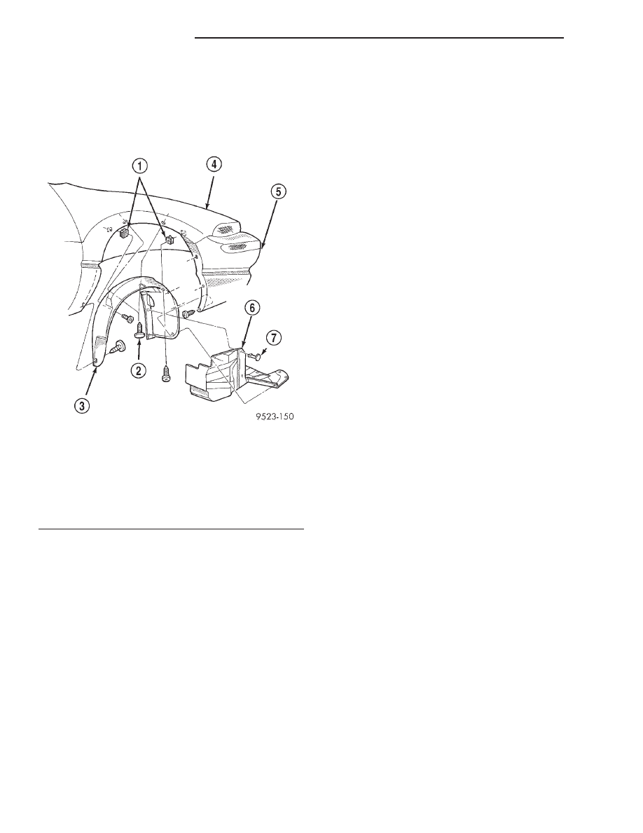
(12) Hoist vehicle and remove right inner splash
shield (Fig. 30).
(13) Remove accessory drive belts. Refer to Group
7, Cooling System for procedure.
(14) Remove axle shafts. Refer to Group 2, Suspen-
sion and Driveshafts for procedure.
(15) Disconnect exhaust pipe from manifold.
(16) Remove front and rear engine mount through
bolts.
(17) Lower vehicle. Remove air cleaner assembly.
(18) Remove power steering pump and reservoir
and set aside.
(19) Remove A/C compressor.
(20) Remove ground straps to body.
(21) Raise vehicle enough to allow engine dolly
and cradle Special Tools 6135 and 6710 to be
installed under vehicle.
(22) Loosen engine support posts to allow move-
ment for positioning onto engine locating holes and
flange on the engine bedplate. Lower vehicle and
position cradle until the engine is resting on support
posts (Fig. 31). Tighten mounts to cradle frame. This
will keep support posts from moving when removing
or installing engine and transmission.
(23) Install safety straps around the engine to cra-
dle; tighten straps and lock them into position.
(24) Raise vehicle enough to see if straps are tight
enough to hold cradle assembly to engine.
(25) Lower vehicle so weight of the engine and
transmission ONLY is on the cradle assembly.
(26) Remove right and left engine/transmission
mount vertical bolts.
(27) Raise vehicle slowly. It may be necessary to
move the engine/transmission assembly with the cra-
dle to allow for removal around body flanges.
INSTALLATION
(1) Position engine and transmission assembly
under vehicle and slowly lower the vehicle over the
engine and transmission.
(2) Align
engine
and
transmission
mounts
to
attaching points. Install mounting bolts at the right
and left engine/transmission mounts. Refer to proce-
dures outlined in this section.
(3) Remove safety straps from engine and trans-
mission assembly. Slowly raise vehicle enough to
remove the engine dolly and cradle.
(4) Install axle shafts. Refer to Group 2, Suspen-
sion and Driveshafts for procedure.
(5) Install transmission and engine braces and
splash shields.
(6) Connect exhaust system to manifold. Refer to
Group 11, Exhaust System for procedure.
(7) Install power steering pump and reservoir.
Refer to Group 7, Cooling System Accessory Drive
Section for belt tension adjustment.
(8) Install A/C compressor and hoses. Refer to
Group 24, Heater and Air Conditioning for procedure.
(9) Install accessory drive belts. Refer to Group 7,
Cooling System Accessory Drive Section for belt ten-
sion adjustment.
(10) Install front and rear engine mount through
bolts.
(11) Install inner splash shield and front wheels.
(12) Manual Transmission: Connect clutch cable
and linkages. Refer to Group 6, Clutch for procedure.
(13)
Automatic Transmission: Connect shifter
linkage. Refer to Group 21, Transaxle for procedures.
(14) Connect fuel line and heater hoses.
(15) Install ground straps. Connect engine and
throttle body electrical connections and harnesses.
Refer to Group 8, Electrical for procedure.
(16) Connect throttle body linkage. Refer to Group
14, Fuel System for procedure.
(17) Install radiator and fan module. Install radia-
tor hoses. Fill cooling system. Refer to Group 7, Cool-
ing System for filling procedure.
Fig. 30 Right Inner Splash Shield
1 – NUT-SNAP
2 – PUSH-IN FASTENER
3 – WHEELHOUSE SPLASH SHIELD
4 – FENDER
5 – FASCIA
6 – ACCESSORY DRIVE BELT SPLASH SHIELD
7 – PUSH-IN FASTENER
9 - 24
2.0L SOHC ENGINE
JX
REMOVAL AND INSTALLATION (Continued)
Нет комментариевНе стесняйтесь поделиться с нами вашим ценным мнением.
Текст