Daewoo Musso. Manual — part 81
OM600 ENGINE MECHANICAL 1B3-31
Assembly Procedure
Notice
In case the prechambers are reused, inspect the
prechambers thoroughly, if the ball pin by heat and fire is
broken, it can not be used.
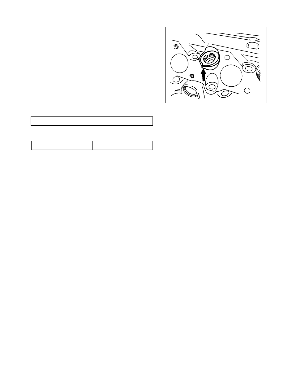
1. Clean the sealing surface of the prechamber.
2. Insert the prechamber into the cylinder head at the same
time aligning the cam on the collar of the prechambers with
the slots in the cylinder head.
Notice
If the spacer rings are fitted to the prechambers, the spacer
rings should be replaced with rings of the same thickness.
Thickness of Spacer Ring
0.3, 0.6, 1.0 mm
3. Coat the threaded ring with oil and assemble the ring by
using the serration wrench.
Tightening Torque
130 Nm

1B3-32 OM600 ENGINE MECHANICAL
MILLING OF PRECHAMBER SEALING SURFACE
1 Drift
2 Sleeve
3 Milling Cutter
4 Counter Sink (Special Tool - 601 589 00 66)
5 Cylinder Head
Tightening Torque
0.3, 0.6, 1.0 mm
Milling of the Prechamber Sealing Surface
Notice
The prechamber sealing surface may only be remachined
once with the cylinder head fitted. It is essential to adhere
to the specified projection ‘C’ of the prechamber of 7.6 -
8.1mm.
This ensures that the required clearance exists between
prechamber and piston crown with the piston in TDC. For
this reason, spacer rings should be inserted on remachined
sealing surfaces.
If a spacer ring is already fitted, or a marking is made on the
cylinder head, the cylinder head must be removed and size
‘C’ measured if further remachining is necessary on a
prechamber sealing surface.
Tools Required
601 589 00 66 00 Counter Sink
667 589 00 23 00 Height Gauge
OM600 ENGINE MECHANICAL 1B3-33
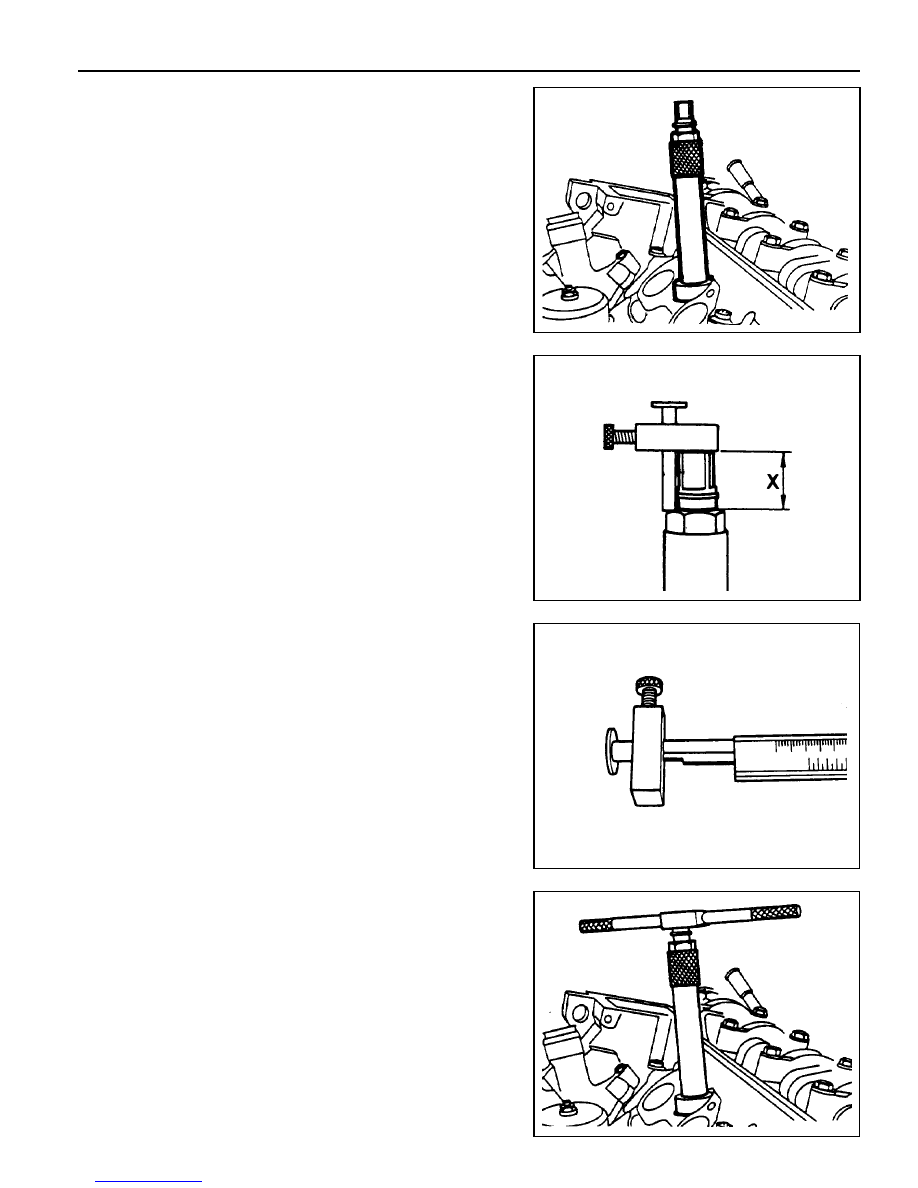
6. Measure the ‘X’ by using a vernier caliper.
7. Mount the turning tool onto the countersink tool and rotate
to the right approx. 5 revolutions by applying slight pressure.
1. Remove the injection nozzle.
2. Remove the prechamber.
3. Cover the prechamber bore to avoid any chips dropping
into the combustion chamber.
4. Remove the protective sleeve from the countersink and
rotate the countersink into the prechamber bore to be
machined as far as the stop.
Counter Sink 601 589 00 66 00
5. Maintain size ‘X’ from the top edge of mandrel to the top
edge of the sleeve with the gauge.
Height Gauge 667 589 00 23 00

1B3-34 OM600 ENGINE MECHANICAL
8. Remeasure size ‘X’ and compare it with the first
measurement and determine the thickness of spacer ring.
Size before machining
25.7 mm
Size after machining
25.5 mm
Ex
The spacer ring should be selected so that it is at least
0.1mm and not more than 0.3mm thicker than the
measured on the sealing surface. In this example, the
necessary thickness of spacer ring should be within
0.3 ~ 0.5mm and the thickness of spacer ring to be
installed is 0.3mm.
9. Remove the countersink tool and clean the chips.
Notice
If the sealing surface is not completely flat, remachine the
sealing surface.
10. emove rag from the prechamber bore and crank the engine
with starter motor to threw out any chips which may have
got into the combustion chamber.
11. Insert the proper spacer ring into the prechamber sealing
surface.
12. Punch a mark on the cylinder head above the prechamber
sealing surface which has been machined.
13. Install the prechambers.
Notice
If the cylinder head is removed, the projection ‘C’ is
measured in place of size ‘X’ and the appropriate size of
spacer ring selected.
Normal Projection (c)
7.6 - 8.1mm
Нет комментариевНе стесняйтесь поделиться с нами вашим ценным мнением.
Текст