Daewoo Musso. Manual — part 82
OM600 ENGINE MECHANICAL 1B3-35
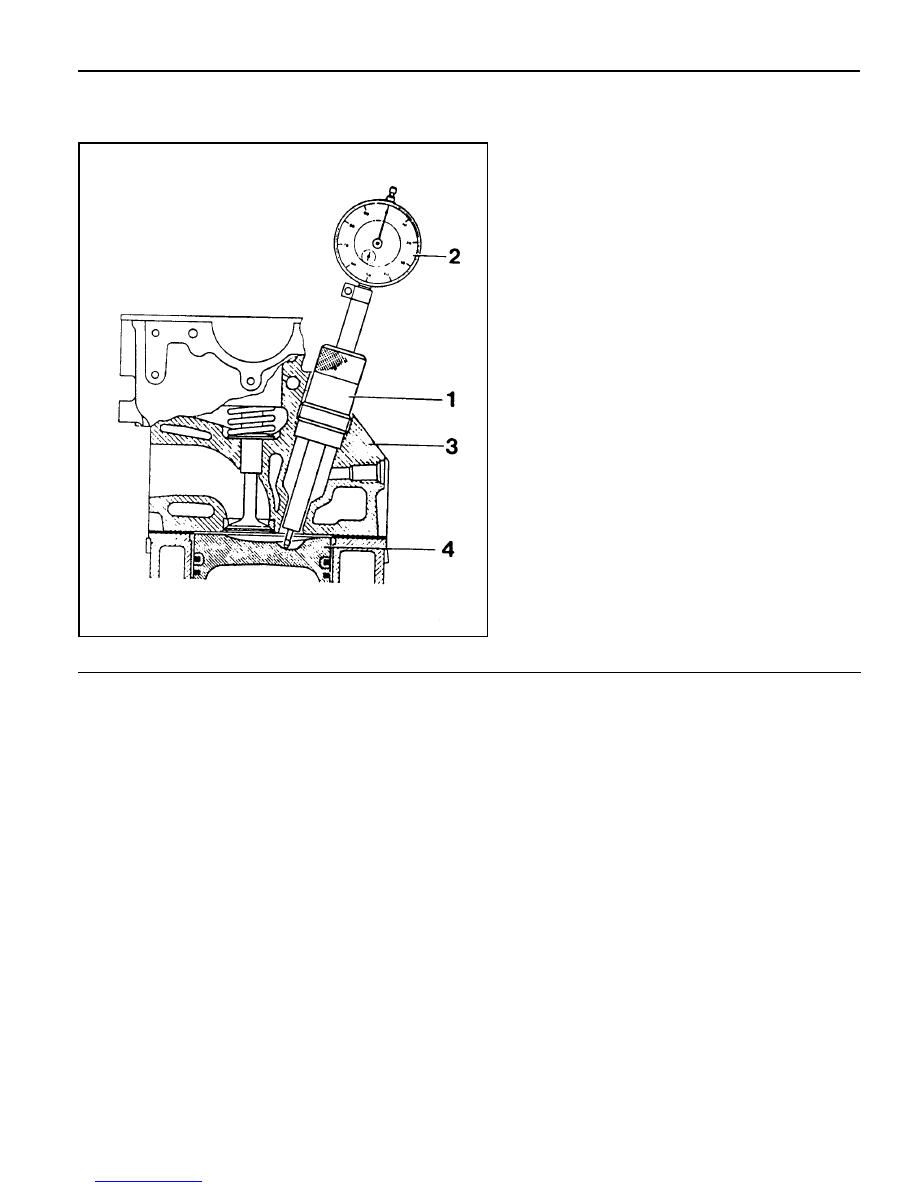
TDC (TDC SENSOR BRACKET) SETTING
Preceding Work : Removal of No.1 cylinder prechamber
1 Measuring Device
2 Dial Gauge
3 Cylinder Head
4 Piston . . . . . . . . . . . . Set at TDC
Tools Service
001 589 32 21 00 Dial Gauge
601 589 07 21 00 Deqth Gauge
667 589 01 21 00 Fixing Device
Notice
l
The TDC sensor bracket must be adjusted in case of
followings.
l
When replacing the TDC sensor bracket.
l
When replacing the crankshaft, the hub or the vibration
damper.
l
When replacing or installing the timing case cover.
l
After engine overhauling.
*
If the cylinder head is removed, the measuring pin of the
dial gauge can be positioned on the piston crown.
This is done by placing the magnetic dial holder on the
mating surface of the crankcase.

1B3-36 OM600 ENGINE MECHANICAL
Setting (with cylinder head installed)
1. Remove the prechamber of No. 1 cylinder.
2. Position the piston of No.1 cylinder at BTDC 10.
3. Install the measuring device into the prechamber bore and
position the dial gauge with a preload of 5mm.
Dial Gauge 001 589 53 21 00
Depth Gauge 601 589 07 21 00
4. Slowly rotate the crankshaft in the direction of engine rotation
until the large pointer on the dial gauge stops (TDC position).
Notice
The position of TDC is when the large pointer on the dial
gauge is stopped before moving back.
5. remove the reinstall the measuring device and position the
dial gauge scale at ‘0’.
6. Slowly rotate the crankshaft in the direction of engine rotation
until the dial gauge has moved back (counterclockwise) by
3.65mm.
7. Insert fixing device into the sensor bracket.
Notice
The pin on the vibration damper must engage into the slot
of the fixing device.
Fixing Device 667 589 01 21 00
8. If the pin does not engage, adjust the setting of the sensor
bracket by removing and tightening of the sensor bracket
bolts.
Tightening Torque
10 Nm
Notice
The timing mark on the damper must be positioned at ATDC
20.
OM600 ENGINE MECHANICAL 1B3-37
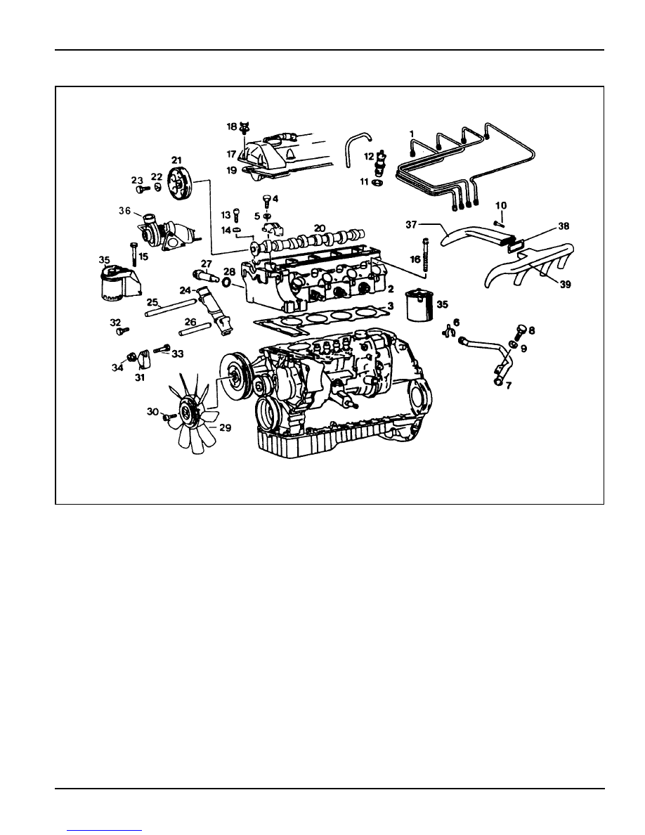
CYLINDER HEAD
1 Fuel Injection Pipe . . . . . . . . . . 18Nm
2 Cylinder Head
3 Gasket . . . . . . . . . . . . ... Replace
4 Bolt . . . . . . . . . . . . . . . 25Nm
5 Washer
6 Clamp
7 Heater Feed Pipe
8 Bolt
9 Washer
10 Bolt
11 Nozzle Washer . . . . . . . . . ... Replace
12 Fuel Injection Nozzle . . . . . . . 35-40 Nm
13 Hexagon Socket Bolt . . . . . . . . . 25 Nm
14 Washer
15 Bolt . . . . . . . . . . . . . . ... 25 Nm
16 Cylinder Head Bolt . . . . . . . .. See Table
17 Cylinder Head Cover
18 Bolt . . . . . . . . . . . . . . ... 10 Nm
19 Gasket
20 Camshaft
21 Camshaft Drive Sprocket . . . . . ... Replace
22 Washer
23 Bolt(12-Sided) . . . . . . . . .. 25Nm + 90°
24 Sliding Rail
25 Sliding Rail Pin
26 Sliding Rail Pin
27 Chain Tensioner . . . . . . . . . ... 80 Nm
28 Gasket . . . . . . . . . . . . ... Replace
29 Cooling Fan . . . . . . . . . . . .. Check
30 Hexagon Socket Bolt . . . . . . . . . 45 Nm
31 Tensioning Lever
32 Bolt . . . . . . . . . . . . . . ... 25 Nm
33 Bolt
34 Nut . . . . . . . . . . . . . . . 23 Nm
35 Fuel Filter
36 Turbo Charger
37 Intake Duct
38 Gasket . . . . . . . . . . . . ... Replace
39 Intake Manifold
1B3-38 OM600 ENGINE MECHANICAL
000 589 77 03 00 Box Wrench Insert
001 589 65 09 00 Socket Wrench Insert
102 589 03 40 00 Magnetic Bar
116 589 02 34 00
Threaded Pin
116 589 03 07 00
T Type Socket Wrench
116 589 20 33 00
Sliding Hammer
601 589 00 10 00 Cylinder Head Bolt Wrench
602 589 00 40 00 Engine Lock
603 589 00 40 00 Counter Holder
Tools Required
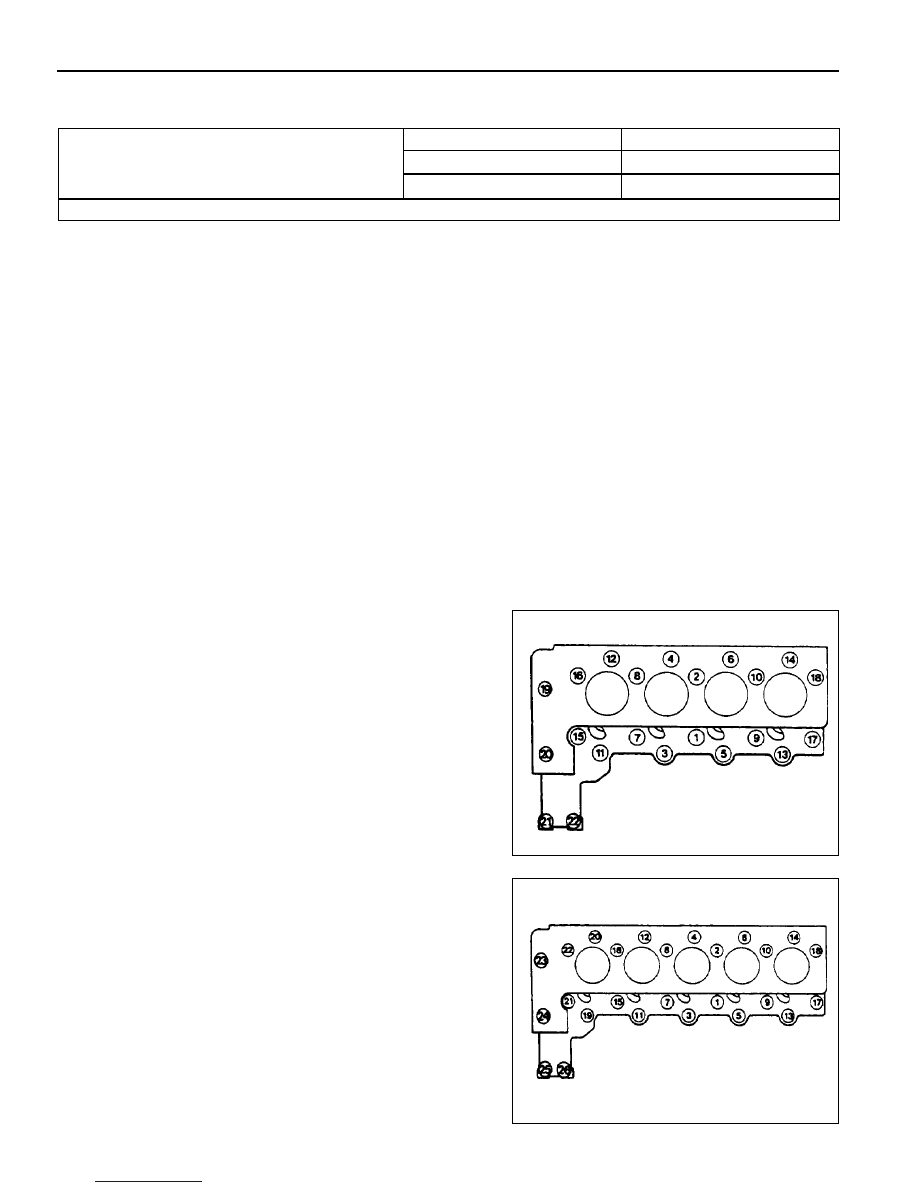
Cylinder Bolts (12-sided socket head)
(Engine cold)
M8 Cylinder Head Bolts
Tightening Torque
stage1
stage2
stage3
10 Nm
35 Nm
180°
25 Nm
Tightening Sequence for Cylinder Head Bolts
OM 662LA Engine
OM 661LA Engine
Нет комментариевНе стесняйтесь поделиться с нами вашим ценным мнением.
Текст