Chery Tiggo 5 (T21). Service manual — part 172
15–
23
15
DTC
B1500-13 Driver Door Outside LF Antenna Circuit Open
DTC
B1501-13 Passenger Door Outside LF Antenna Circuit Open
DTC
B1516-19 HSU Overload
DTC
B1517-23 HSU Switch Continuously Pressed Failure
15–
24
15
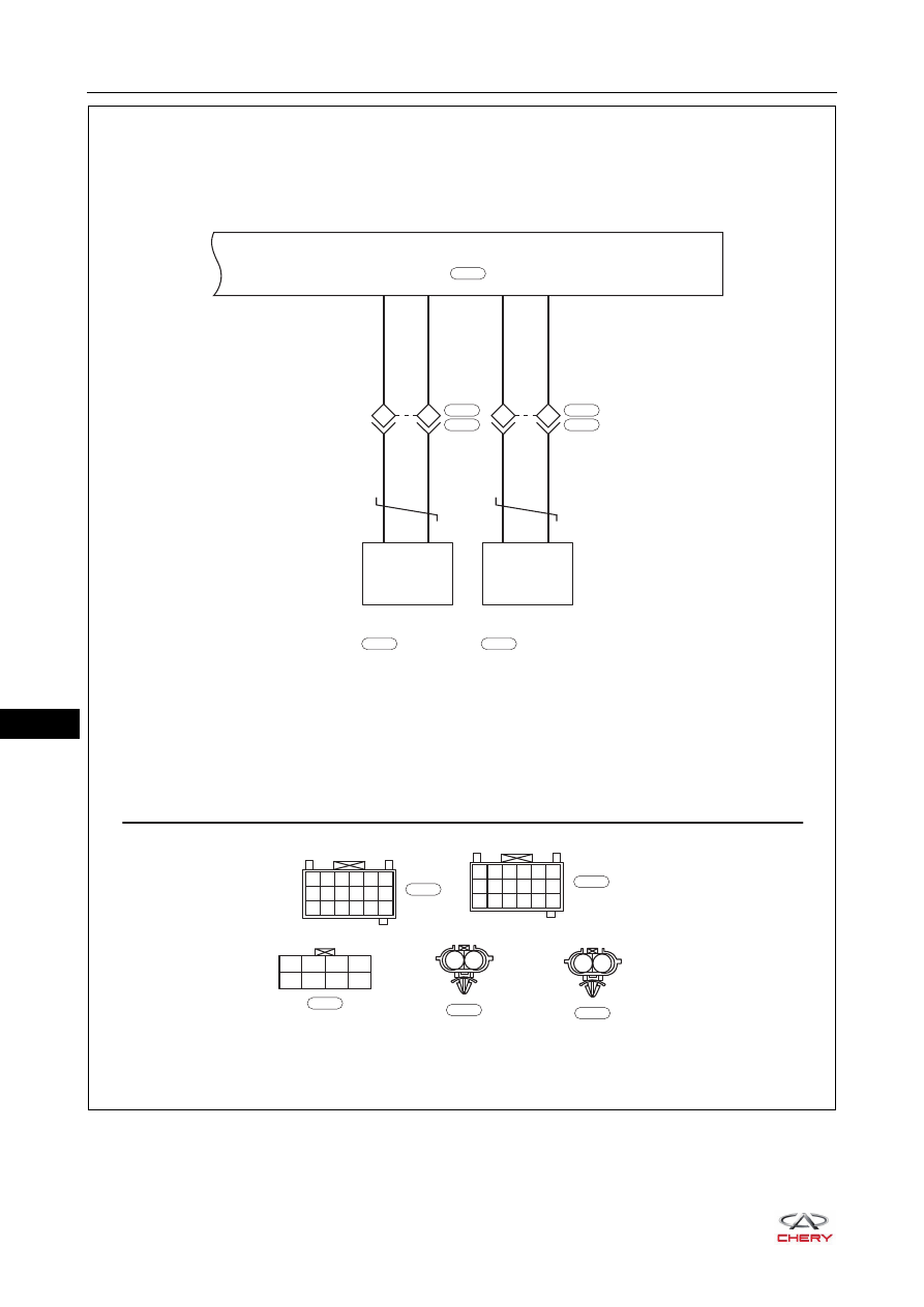
ET21140060
CVT
RW
RW
J303
2
12
LY
LY
J302
1
9
F-007
B-040
LEFT HANDLE
SENSOR
F-003
LB
LB
J307
2
18
BG
BG
J306
1
10
H-002
B-061
RIGHT HANDLE
SENSOR
H-004
J304 J303 J302 J301
J308 J307 J306 J305
B
B-056
PEPS (J3)
B-056
1
4
7 10 13 16
2
5
8 11 14 17
3
6
9 12 15 18
W
B-040
1
2
B
F-003
1
2
B
H-004
1
4
7 10 13 16
2
5
8 11 14 17
3
6
9 12 15 18
W
B-061
15–
25
15
DTC Confirmation Procedure
Confirm that battery voltage is normal before performing the following procedures.
Turn ignition switch to LOCK.
Connect X-431 3G diagnostic tester (the latest software) to Data Link Connector (DLC).
Turn ignition switch ON.
Use X-431 3G diagnostic tester to record and clear the DTCs stored in the PEPS system.
Turn ignition switch to LOCK and wait for a few seconds.
Use X-431 3G diagnostic tester to select "Read Code".
If DTC is detected, the malfunction indicated by the DTC is current. Go to the diagnosis procedure - Step 1.
If DTC is not detected, the malfunction indicated by the DTC is intermittent (
).
Diagnosis Procedure
a. Turn off all the electrical equipment and ignition switch.
b. Disconnect the negative battery cable.
c. Disconnect the left handle sensor F-003 and right handle sensor H-004.
d. Disconnect the PEPS controller connector B-056.
e. Disconnect the front left door wire harness connector F-007 and body wire harness connector B-040.
f. Disconnect the front right door wire harness connector H-002 and body wire harness connector B-061.
g. Check if wire harnesses are worn, pierced, pinched or partially broken.
h. Look for broken, bent, protruded or corroded terminals.
i. Check that the related connector pins are in good condition.
DTC Code
DTC Definition
DTC Detection
Condition
Possible Cause
B1500-13
Driver Door Outside LF
Antenna Circuit Open
Engine switch ON
Wire harness or connector damaged
Outside low frequency antenna on
driver side
Outside low frequency antenna on
passenger side
Passive Entry & Passive Start (PEPS)
controller
B1501-13
Passenger Door
Outside LF Antenna
Circuit Open
B1516-19
HSU Overload
B1517-23
HSU Switch
Continuously Pressed
Failure
CAUTION
When performing electrical equipment diagnosis and test, always refer to the circuit diagram for related
circuit and component information.
1
Check wire harness and connector
Repair or replace related wire harness and
connector
NG
OK
15–
26
15
a. Check the body wire harness and connector (outside low
frequency antenna on driver side).
Check for Open
Check for Short
b. Check the body wire harness and connector (outside low
frequency antenna on passenger side)
Check for Open
Check for Short
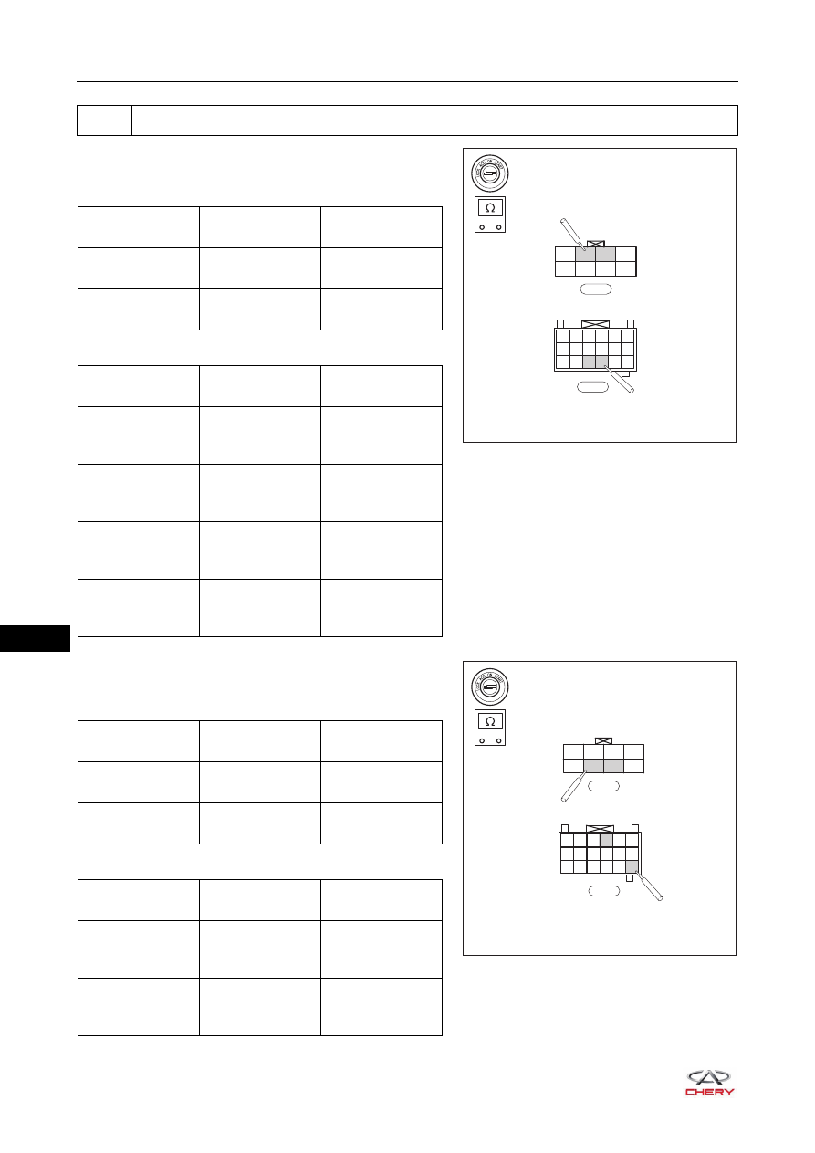
2
Check body wire harness and connector
-
+
RT21150210
J304 J303 J302 J301
J308 J307 J306 J305
B-056
1
4
7 10 13 16
2
5
8 11 14 17
3
6
9 12 15 18
B-040
Multimeter
Connection
Condition
Specified
Condition
B-056 (J303) -
B-040 (12)
Always
Continuity
B-056 (J302) -
B-040 (9)
Always
Continuity
Multimeter
Connection
Condition
Specified
Condition
B-056 (J303) or
B-040 (12) - Body
ground
Always
No continuity
B-056 (J302) or
B-040 (9) - Body
ground
Always
No continuity
B-056 (J303) or
B-040 (12) -
Battery positive
Always
No continuity
B-056 (J302) or
B-040 (9) -
Battery positive
Always
No continuity
-
+
RT21150230
J304 J303 J302 J301
J308 J307 J306 J305
B-056
1
4
7 10 13 16
2
5
8 11 14 17
3
6
9 12 15 18
B-061
Multimeter
Connection
Condition
Specified
Condition
B-056 (J307) -
B-061 (18)
Always
Continuity
B-056 (J306) -
B-061 (10)
Always
Continuity
Multimeter
Connection
Condition
Specified
Condition
B-056 (J307) or
B -061 (18) - Body
ground
Always
No continuity
B-056 (J306) or
B-061 (10) - Body
ground
Always
No continuity
Нет комментариевНе стесняйтесь поделиться с нами вашим ценным мнением.
Текст