Chery Tiggo 5 (T21). Service manual — part 171
15–
19
15
Problem Repair (No DTC)
If PEPS system has problems, but no DTC is stored in PEPS system, this problem is called a problem without
DTC.
Troubleshooting recommendation: check corresponding components according to problem symptom, and
troubleshoot following the vehicle repair manual.
Diagnostic Help
1. Connect X-431 3G diagnostic tester (the latest software) to Data Link Connector (DLC), and make it
communicate with vehicle electronic module by the data network.
2. Confirm that malfunction is current, and carry out diagnostic test and repair procedures.
3. If DTC cannot be deleted, the malfunction is current.
4. Visually check the related wire harness and connector.
5. Check and clean all wire harness connectors and grounds related to current DTC.
6. If multiple trouble codes were set, refer to the circuit diagrams to look for any common ground circuit or
power supply circuit applied to the DTC.
7. Refer to any Technical Bulletin that may apply to the malfunction.
Intermittent DTC Troubleshooting
If malfunction is intermittent, perform the followings:
Check if connectors are loose.
Check if wire harnesses are worn, pierced, pinched or partially broken.
Wiggle related wire harnesses and connectors and observe if signal is interrupted in the related circuit.
If possible, try to duplicate the conditions under which the DTC was set.
Look for the data that has changed or the DTC to be reset during the wiggle test.
Look for broken, bent, protruded or corroded terminals.
Check and clean all wire harness connectors and grounding parts related to the current DTC.
Remove the PEPS controller from the malfunctioning vehicle and install it to a new vehicle and perform a
test. If DTC cannot be cleared, the PEPS controller is malfunctioning. If DTC can be cleared, reinstall the
PEPS controller to original vehicle.
If multiple trouble codes were set, refer to the circuit diagrams to look for any common ground circuit or
power supply circuit applied to the DTC.
Refer to Technical Bulletin that is applied to the malfunction.
Symptom
Suspected Area
Instrument cluster indicator does not come on or
remains on
Instrument cluster indicator (broken)
Wire harness (incorrectly connected)
15–
20
15
Ground Inspection
Groundings are very important to entire circuit system, which are normal or not can seriously affect the entire
circuit system. Ground points are often exposed to moisture, dirt and other corrosive environments. Corrosion
(rust) and oxidation may increase load resistance. This situation will seriously affect the normal operation of
the circuit. The operations to check the ground points are as follows:
1. Remove the ground bolt or nut.
2. Check all contact surfaces for tarnish, dirt and rust, etc.
3. Clean as necessary to ensure that contacting is in a good condition.
4. Reinstall the ground bolt or nut securely.
5. Check if add-on accessories interfere with the ground circuit.
6. If several wire harnesses are crimped into one ground terminal, check if they are installed correctly. Make
sure all wire harnesses are clean, securely fastened and providing a good ground path.
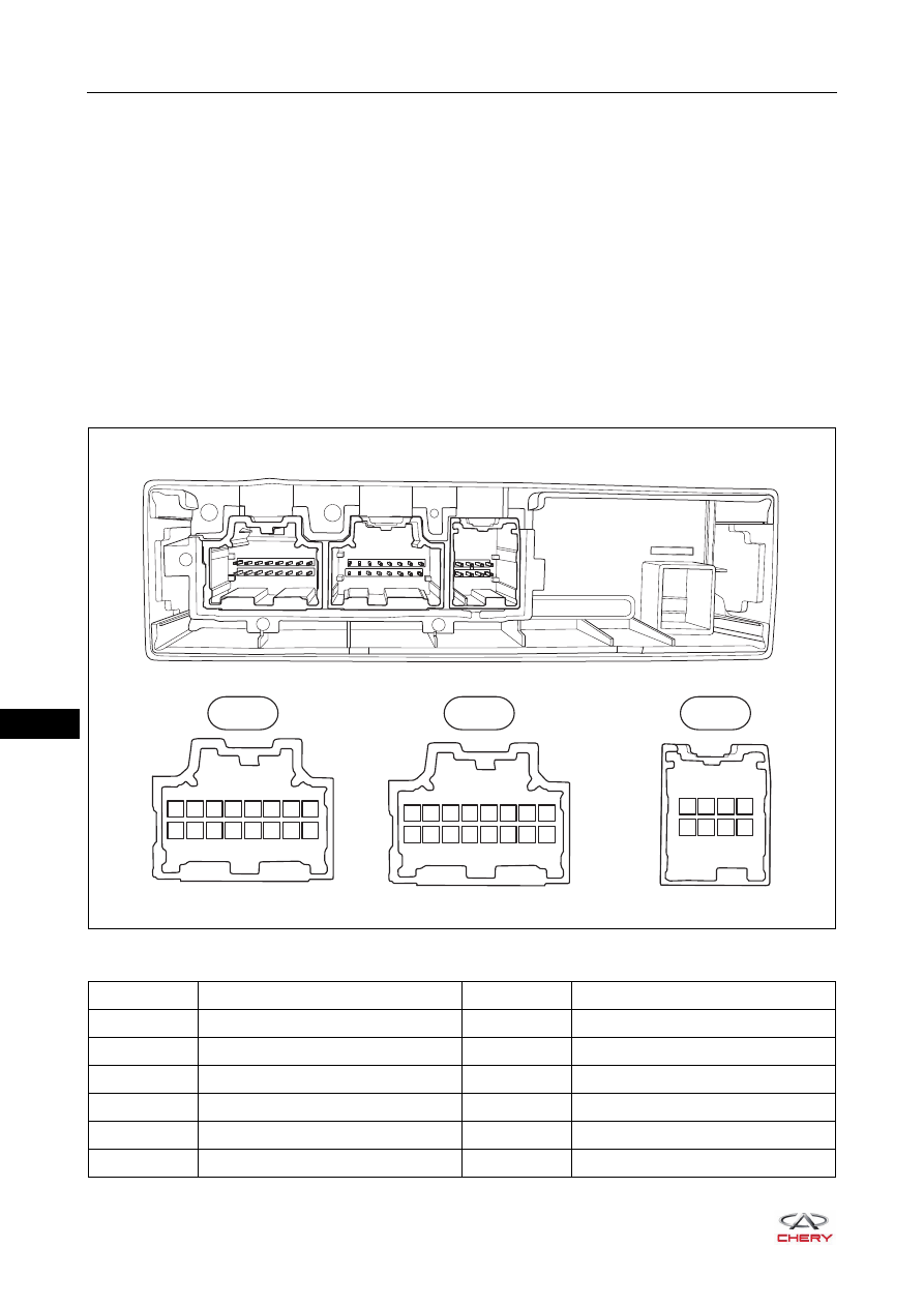
Passive Entry & Passive Start (PEPS) Controller Terminal List
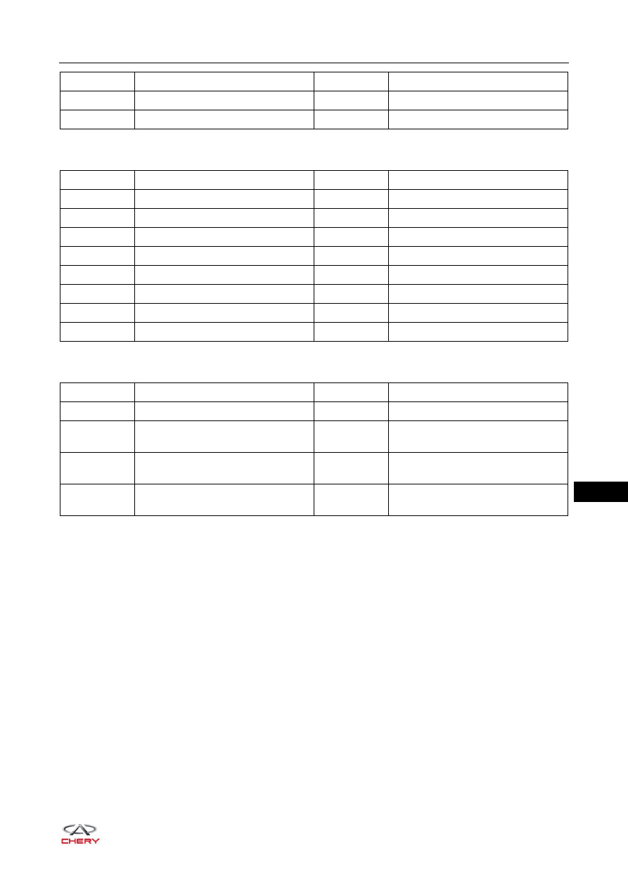
Connector J1 Terminal Definition
RT21150050
J1
J2
J3
J101 J102 J103 J104 J105 J106 J107 J108
J109 J110 J111 J112 J113 J114 J115 J116
J1
J201 J202 J203 J204 J205 J206 J207 J208
J209 J210 J211 J212 J213 J214 J215 J216
J2
J301 J302 J303 J304
J305 J306 J307 J308
J3
Terminal No.
Terminal Definition
Terminal No.
Terminal Definition
J101
Battery Power Supply
J109
Clutch Switch Signal
J102
IG1 Relay Drive (High)
J110
Starter Relay Inspection
J103
ACC Relay Drive (High)
J111
Ignition Signal
J104
IG2 Relay Drive (High)
J112
-
J105
CAN-L
J113
Starter Relay (High)
J106
CAN-H
J114
Gear Position Signal
15–
21
15
Connector J2 Terminal Definition
Connector J3 Terminal Definition
J107
Hard Wire Speed Signal
J115
-
J108
-
J116
GND
Terminal No.
Terminal Definition
Terminal No.
Terminal Definition
Terminal No.
Terminal Definition
Terminal No.
Terminal Definition
J201
Anti-theft Coil Positive
J209
-
J202
Anti-theft Coil Negative
J210
Engine Switch Ground
J203
Engine Switch Indicator (Green)
J211
Engine Switch 1
J204
Engine Switch Backlight (White)
J212
-
J205
Engine Switch Indicator (Amber)
J213
Engine Switch 2
J206
Low Frequency Antenna 1 Negative
J214
Low Frequency Antenna 1 Positive
J207
Low Frequency Antenna 2 Negative
J215
Low Frequency Antenna 3 Negative
J208
Low Frequency Antenna 2 Positive
J216
Low Frequency Antenna 3 Positive
Terminal No.
Terminal Definition
Terminal No.
Terminal Definition
J301
Back Door Unlock Signal
J305
-
J302
Front Left Door Handle Sensor (Low
Frequency Antenna) Negative
J306
Front Right Door Handle Sensor
(Low Frequency Antenna) Negative
J303
Front Left Door Handle Sensor (Low
Frequency Antenna) Positive
J307
Front Right Door Handle Sensor
(Low Frequency Antenna) Positive
J304
Back Door Low Frequency Antenna
Negative
J308
Back Door Low Frequency Antenna
Positive
15–
22
15
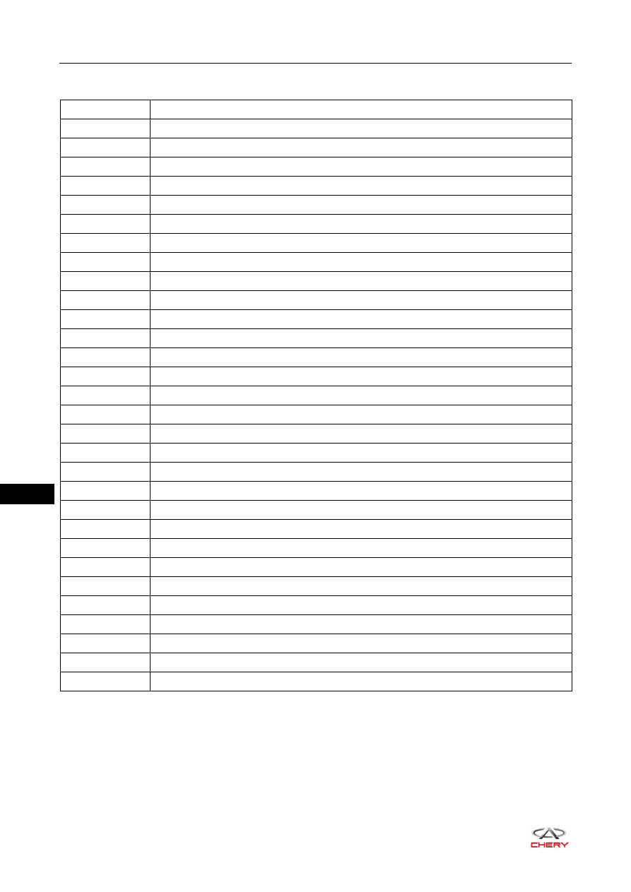
Diagnostic Trouble Code (DTC) Chart
DTC Code
DTC Definition
B1500-13
Driver Door Outside LF Antenna Circuit Open
B1501-13
Passenger Door Outside LF Antenna Circuit Open
B1502-13
Front Internal LF Antenna Circuit Open
B1503-13
Middle Internal LF Antenna Circuit Open
B1504-13
Rear Internal LF Antenna Circuit Open
B1505-13
Bumper LF Antenna Circuit Open
B1506-00
Abnormality ON Switches of Engine Switch No Subtype Information
B1507-00
Abnormality in IG Circuit No Subtype Information
B1508-00
Abnormality in ACC Circuit No Subtype Information
B1509-00
Abnormality in Brake Signal No Subtype Information
B150A-00
Abnormality in Vehicle Speed Signal No Subtype Information
B150C-00
Clutch Switch Signal Error No Subtype Information
B150D-00
Abnormality on ESCL LCK_GND No Subtype Information
B150E-00
Abnormality on ESCL LCK_PS No Subtype Information
B150F-00
ESCL Anti-scanning No Subtype Information
B1510-00
Abnormality on Wheel Speed Signal No Subtype Information
B1511-00
Abnormality in ESCL Lock No Subtype Information
B1512-00
Abnormality in ESCL Unlock No Subtype Information
B1513-00
ESCL External Failure No Subtype Information
B1514-00
Abnormality on STAR Power Supply No Subtype Information
B1515-45
ROM for Checksum Failure
B1516-19
HSU Overload
B1517-23
HSU Switch Continuously Pressed Failure
U0073-88
Control Module Communication Bus Off
U0100-87
Lost Communication with EMS Missing Message
U0101-87
Lost Communication with TCM Missing Message
U0129-87
Lost Communication with BSM Missing Message
U0140-87
Lost Communication with BCM Missing Message
U0329-87
Lost Communication with ESCL Missing Message
U1300-55
Software Configuration Error Not Configured
Нет комментариевНе стесняйтесь поделиться с нами вашим ценным мнением.
Текст