Nissan Murano Z51. Instruction — part 555
EC-228
< DTC/CIRCUIT DIAGNOSIS >
[VQ35DE]
P0172, P0175 FUEL INJECTION SYSTEM FUNCTION
6.
Also check harness for short to power.
Is the inspection result normal?
YES
>> GO TO 4.
NO
>> Repair open circuit, short to ground or short to power in harness or connectors.
4.
CHECK FUEL PRESSURE
1.
Release fuel pressure to zero. Refer to
2.
Install fuel pressure gauge kit [SST (J-44321)] and check fuel pressure. Refer to
Is the inspection result normal?
YES
>> GO TO 5.
NO
>> Replace “fuel filter and fuel pump assembly”.
5.
CHECK MASS AIR FLOW SENSOR
With CONSULT-III
1.
Install all removed parts.
2.
Check “MASS AIR FLOW” in “DATA MONITOR” mode with CONSULT-III.
For specification, refer to
EC-536, "Mass Air Flow Sensor"
With GST
1.
Install all removed parts.
2.
Check mass air flow sensor signal in “Service $01” with GST.
For specification, refer to
EC-536, "Mass Air Flow Sensor"
Is the measurement value within the specification?
YES
>> GO TO 6.
NO
>> Check connectors for rusted terminals or loose connections in the mass air flow sensor circuit or
ground. Refer to
6.
CHECK FUNCTION OF FUEL INJECTOR
With CONSULT-III
1.
Start engine.
2.
Perform “POWER BALANCE” in “ACTIVE TEST” mode with CONSULT-III.
3.
Check that each circuit produces a momentary engine speed drop.
With GST
1.
Let engine idle.
DTC
A/F sensor 1
Ground
Continuity
Bank
Connector
Terminal
P0172
1
F27
1
Ground
Not existed
2
P0175
2
F64
1
2
DTC
ECM
Ground
Continuity
Connector
Terminal
P0172
F8
45
Ground
Not existed
49
P0175
53
57
At idling: Approximately 350 kPa (3.57 kg/cm
2
, 51 psi)
P0172, P0175 FUEL INJECTION SYSTEM FUNCTION
EC-229
< DTC/CIRCUIT DIAGNOSIS >
[VQ35DE]
C
D
E
F
G
H
I
J
K
L
M
A
EC
N
P
O
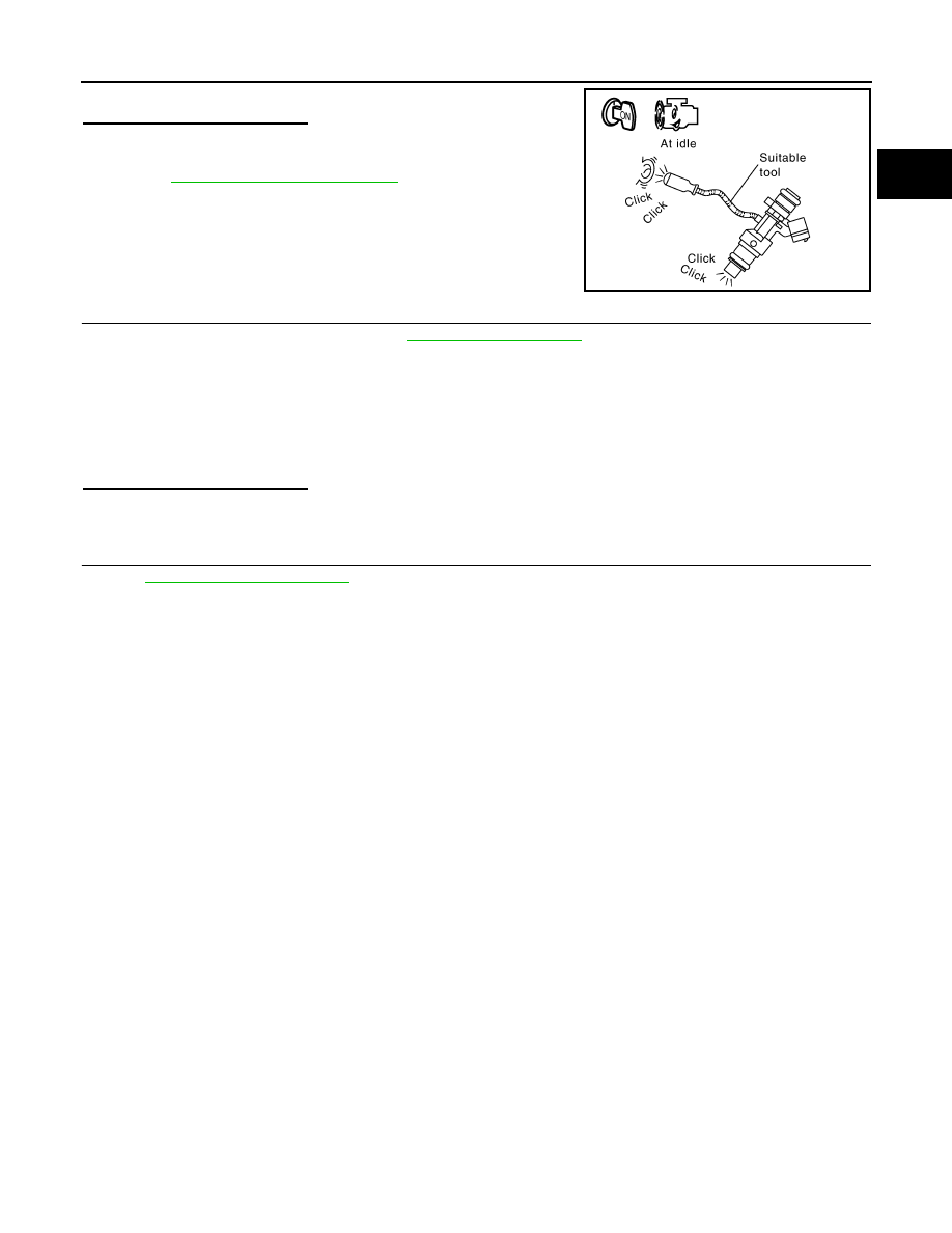
2.
Listen to each fuel injector operating sound.
Is the inspection result normal?
YES
>> GO TO 7.
NO
>> Perform trouble diagnosis for FUEL INJECTOR, refer to
.
7.
CHECK FUEL INJECTOR
1.
Remove fuel injector assembly. Refer to
.
Keep fuel hose and all fuel injectors connected to fuel tube.
2.
Confirm that the engine is cooled down and there are no fire hazards near the vehicle.
3.
Disconnect all fuel injector harness connectors.
4.
Disconnect all ignition coil harness connectors.
5.
Prepare pans or saucers under each fuel injectors.
6.
Crank engine for about 3 seconds.
Check fuel does not drip from fuel injector.
Is the inspection result normal?
YES
>> GO TO 8.
NO
>> Replace the fuel injectors from which fuel is dripping. Always replace O-ring with new one.
8.
CHECK INTERMITTENT INCIDENT
GI-39, "Intermittent Incident"
.
>> INSPECTION END
PBIB3332E
EC-230
< DTC/CIRCUIT DIAGNOSIS >
[VQ35DE]
P0181 FTT SENSOR
P0181 FTT SENSOR
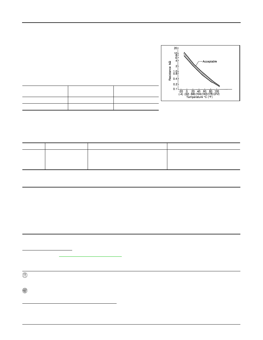
Description
INFOID:0000000005536626
The fuel tank temperature sensor is used to detect the fuel tempera-
ture inside the fuel tank. The sensor modifies a voltage signal from
the ECM. The modified signal returns to the ECM as the fuel temper-
ature input. The sensor uses a thermistor which is sensitive to the
change in temperature. The electrical resistance of the thermistor
decreases as temperature increases.
<Reference data>
*: These data are reference values and are measured between ECM terminals 95 (Fuel tank temperature sensor) and ground.
DTC Logic
INFOID:0000000005536627
DTC DETECTION LOGIC
DTC CONFIRMATION PROCEDURE
1.
PRECONDITIONING
If DTC Confirmation Procedure has been previously conducted, always perform the following before conduct-
ing the next test.
1.
Turn ignition switch OFF and wait at least 10 seconds.
2.
Turn ignition switch ON.
3.
Turn ignition switch OFF and wait at least 10 seconds.
>> GO TO 2.
2.
PERFORM DTC CONFIRMATION PROCEDURE-I
1.
Turn ignition switch ON and wait at least 10 seconds.
2.
Check 1st trip DTC.
Is 1st trip DTC detected?
YES
>> Go to
NO
>> GO TO 3.
3.
CHECK ENGINE COOLANT TEMPERATURE
With CONSULT-III
1.
Select “COOLAN TEMP/S” in “DATA MONITOR” with CONSULT-III.
2.
Check “COOLAN TEMP/S” value.
With GST
Follow the procedure “With CONSULT-III” above.
Is “COOLAN TEMP/S” less than 60
°
C (140
°
F)?
YES
>> INSPECTION END
NO
>> GO TO 4.
4.
PERFORM DTC CONFIRMATION PROCEDURE-II
Fluid temperature
[
°
C (
°
F)]
Voltage*
(V)
Resistance
(k
Ω
)
20 (68)
3.5
2.3 - 2.7
50 (122)
2.2
0.79 - 0.90
SEF012P
DTC No.
Trouble diagnosis name
DTC detecting condition
Possible cause
P0181
Fuel tank temperature
sensor circuit range/per-
formance
Rationally incorrect voltage from the sensor is
sent to ECM, compared with the voltage signals
from engine coolant temperature sensor and in-
take air temperature sensor.
• Harness or connectors
(The sensor circuit is open or shorted)
• Fuel tank temperature sensor
P0181 FTT SENSOR
EC-231
< DTC/CIRCUIT DIAGNOSIS >
[VQ35DE]
C
D
E
F
G
H
I
J
K
L
M
A
EC
N
P
O
With CONSULT-III
1.
Cool engine down until “COOLAN TEMP/S” is less than 60
°
C (140
°
F).
2.
Wait at least 10 seconds.
3.
Check 1st trip DTC.
With GST
Follow the procedure “With CONSULT-III” above.
Is 1st trip DTC detected?
YES
>> Go to
NO
>> INSPECTION END
Diagnosis Procedure
INFOID:0000000005536628
1.
CHECK GROUND CONNECTION
1.
Turn ignition switch OFF.
2.
Check ground connection E38. Refer to Ground Inspection in
.
Is the inspection result normal?
YES
>> GO TO 2.
NO
>> Repair or replace ground connection.
2.
CHECK FUEL TANK TEMPERATURE SENSOR POWER SUPPLY CIRCUIT
1.
Turn ignition switch OFF.
2.
Disconnect “fuel level sensor unit and fuel pump” harness connector.
3.
Turn ignition switch ON.
4.
Check the voltage between “fuel level sensor unit and fuel pump” harness connector and ground.
Is the inspection result normal?
YES
>> GO TO 4.
NO
>> GO TO 3.
3.
DETECT MALFUNCTIONING PART
Check the following.
• Harness connectors E104, B4
• Harness for open or short between ECM and “fuel level sensor unit and fuel pump”
>> Repair open circuit, short to ground or short to power in harness or connector.
4.
CHECK FUEL TANK TEMPERATURE SENSOR GROUND CIRCUIT FOR OPEN AND SHORT
1.
Turn ignition switch OFF.
2.
Disconnect ECM harness connector.
3.
Check the continuity between “fuel level sensor unit and fuel pump” harness connector and ECM harness
connector.
4.
Also check harness for short to ground and short to power.
Is the inspection result normal?
YES
>> GO TO 6.
NO
>> GO TO 5.
5.
DETECT MALFUNCTIONING PART
Check the following.
Fuel level sensor unit and fuel pump
Ground
Voltage
Connector
Terminal
B40
4
Ground
Approx. 5 V
Fuel level sensor unit and fuel pump
ECM
Continuity
Connector
Terminal
Connector
Terminal
B40
5
E16
104
Existed
Нет комментариевНе стесняйтесь поделиться с нами вашим ценным мнением.
Текст