Nissan Murano Z51. Instruction — part 556
EC-232
< DTC/CIRCUIT DIAGNOSIS >
[VQ35DE]
P0181 FTT SENSOR
• Harness connectors E105, M11
• Harness connectors M77, B11
• Harness for open or short between “fuel level sensor unit and fuel pump” and ECM
>> Repair open circuit, short to ground or short to power in harness or connector.
6.
CHECK FUEL TANK TEMPERATURE SENSOR
EC-232, "Component Inspection"
Is the inspection result normal?
YES
>> GO TO 7.
NO
>> Replace “fuel level sensor unit and fuel pump”.
7.
CHECK INTERMITTENT INCIDENT
GI-39, "Intermittent Incident"
>> INSPECTION END
Component Inspection
INFOID:0000000005536629
1.
CHECK FUEL TANK TEMPERATURE SENSOR
1.
Turn ignition switch OFF.
2.
Remove fuel level sensor unit.
3.
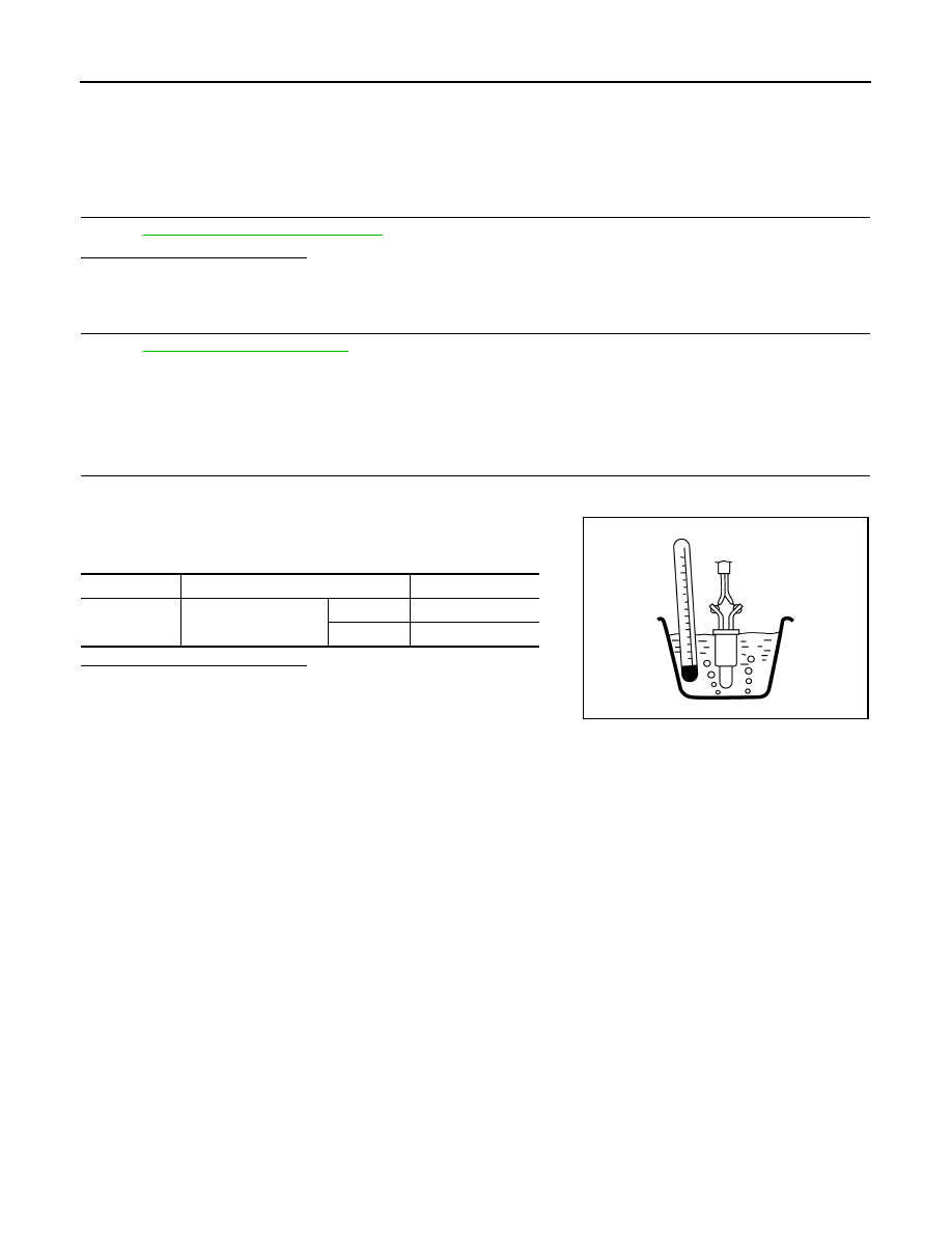
Check resistance between “fuel level sensor unit and fuel pump”
terminals by heating with hot water as shown in the figure.
Is the inspection result normal?
YES
>> INSPECTION END
NO
>> Replace “fuel level sensor unit and fuel pump”.
Terminals
Condition
Resistance
4 and 5
Temperature [
°
C (
°
F)]
20 (68)
2.3 - 2.7 k
Ω
50 (122)
0.79 - 0.90 k
Ω
JMBIA0167ZZ
P0182, P0183 FTT SENSOR
EC-233
< DTC/CIRCUIT DIAGNOSIS >
[VQ35DE]
C
D
E
F
G
H
I
J
K
L
M
A
EC
N
P
O
P0182, P0183 FTT SENSOR
Description
INFOID:0000000005536630
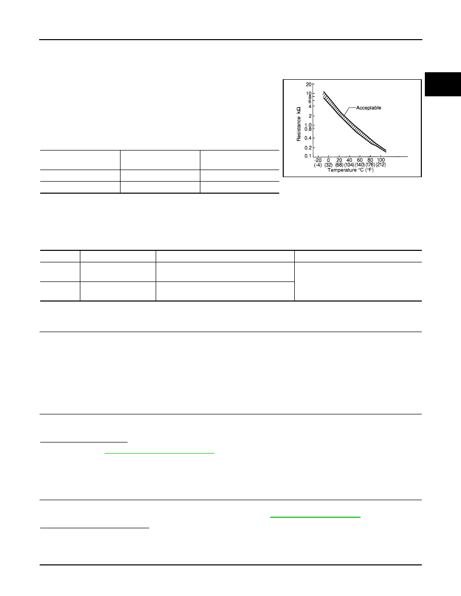
The fuel tank temperature sensor is used to detect the fuel tempera-
ture inside the fuel tank. The sensor modifies a voltage signal from
the ECM. The modified signal returns to the ECM as the fuel temper-
ature input. The sensor uses a thermistor which is sensitive to the
change in temperature. The electrical resistance of the thermistor
decreases as temperature increases.
<Reference data>
*: These data are reference values and are measured between ECM terminals 95 (Fuel tank temperature sensor) and ground.
DTC Logic
INFOID:0000000005536631
DTC DETECTION LOGIC
DTC CONFIRMATION PROCEDURE
1.
PRECONDITIONING
If DTC Confirmation Procedure has been previously conducted, always perform the following before conduct-
ing the next test.
1.
Turn ignition switch OFF and wait at least 10 seconds.
2.
Turn ignition switch ON.
3.
Turn ignition switch OFF and wait at least 10 seconds.
>> GO TO 2.
2.
PERFORM DTC CONFIRMATION PROCEDURE
1.
Turn ignition switch ON and wait at least 5 seconds.
2.
Check 1st trip DTC.
Is 1st trip DTC detected?
YES
>> Go to
NO
>> INSPECTION END
Diagnosis Procedure
INFOID:0000000005536632
1.
CHECK GROUND CONNECTION
1.
Turn ignition switch OFF.
2.
Check ground connection E38. Refer to Ground Inspection in
.
Is the inspection result normal?
YES
>> GO TO 2.
NO
>> Repair or replace ground connection.
2.
CHECK FUEL TANK TEMPERATURE SENSOR POWER SUPPLY CIRCUIT
1.
Turn ignition switch OFF.
Fluid temperature
[
°
C (
°
F)]
Voltage*
(V)
Resistance
(k
Ω
)
20 (68)
3.5
2.3 - 2.7
50 (122)
2.2
0.79 - 0.90
SEF012P
DTC No.
Trouble diagnosis name
DTC detecting condition
Possible cause
P0182
Fuel tank temperature
sensor circuit low input
An excessively low voltage from the sensor is
sent to ECM.
• Harness or connectors
(The sensor circuit is open or shorted.)
• Fuel tank temperature sensor
P0183
Fuel tank temperature
sensor circuit high input
An excessively high voltage from the sensor is
sent to ECM.
EC-234
< DTC/CIRCUIT DIAGNOSIS >
[VQ35DE]
P0182, P0183 FTT SENSOR
2.
Disconnect “fuel level sensor unit and fuel pump” harness connector.
3.
Turn ignition switch ON.
4.
Check the voltage between “fuel level sensor unit and fuel pump” harness connector and ground.
Is the inspection result normal?
YES
>> GO TO 4.
NO
>> GO TO 3.
3.
DETECT MALFUNCTIONING PART
Check the following.
• Harness connectors E104, B4
• Harness for open or short between ECM and “fuel level sensor unit and fuel pump”
>> Repair open circuit, short to ground or short to power in harness or connector.
4.
CHECK FUEL TANK TEMPERATURE SENSOR GROUND CIRCUIT FOR OPEN AND SHORT
1.
Turn ignition switch OFF.
2.
Disconnect ECM harness connector.
3.
Check the continuity between “fuel level sensor unit and fuel pump” harness connector and ECM harness
connector.
4.
Also check harness for short to ground and short to power.
Is the inspection result normal?
YES
>> GO TO 6.
NO
>> GO TO 5.
5.
DETECT MALFUNCTIONING PART
Check the following.
• Harness connectors E105, M11
• Harness connectors M77, B11
• Harness for open or short between “fuel level sensor unit and fuel pump” and ECM
>> Repair open circuit, short to ground or short to power in harness or connector.
6.
CHECK FUEL TANK TEMPERATURE SENSOR
EC-234, "Component Inspection"
Is the inspection result normal?
YES
>> GO TO 7.
NO
>> Replace “fuel level sensor unit and fuel pump”.
7.
CHECK INTERMITTENT INCIDENT
GI-39, "Intermittent Incident"
>> INSPECTION END
Component Inspection
INFOID:0000000005536633
1.
CHECK FUEL TANK TEMPERATURE SENSOR
1.
Turn ignition switch OFF.
Fuel level sensor unit and fuel pump
Ground
Voltage
Connector
Terminal
B40
4
Ground
Approx. 5 V
Fuel level sensor unit and fuel pump
ECM
Continuity
Connector
Terminal
Connector
Terminal
B40
5
E16
104
Existed
P0182, P0183 FTT SENSOR
EC-235
< DTC/CIRCUIT DIAGNOSIS >
[VQ35DE]
C
D
E
F
G
H
I
J
K
L
M
A
EC
N
P
O
2.
Remove fuel level sensor unit.
3.
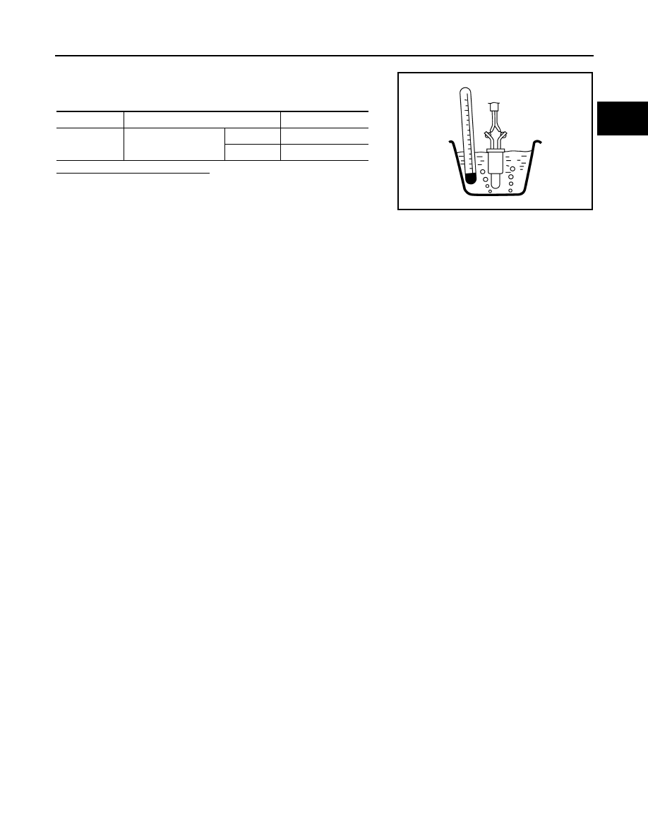
Check resistance between “fuel level sensor unit and fuel pump”
terminals by heating with hot water as shown in the figure.
Is the inspection result normal?
YES
>> INSPECTION END
NO
>> Replace “fuel level sensor unit and fuel pump”.
Terminals
Condition
Resistance
4 and 5
Temperature [
°
C (
°
F)]
20 (68)
2.3 - 2.7 k
Ω
50 (122)
0.79 - 0.90 k
Ω
JMBIA0167ZZ
Нет комментариевНе стесняйтесь поделиться с нами вашим ценным мнением.
Текст