Nissan Murano Z51. Instruction — part 553
EC-220
< DTC/CIRCUIT DIAGNOSIS >
[VQ35DE]
P0139, P0159 HO2S2
With CONSULT-III
1.
Turn ignition switch ON and select “DATA MONITOR” mode with CONSULT-III.
2.
Start engine and warm it up to the normal operating temperature.
3.
Turn ignition switch OFF and wait at least 10 seconds.
4.
Start engine and keep the engine speed between 3,500 and 4,000 rpm for at least 1 minute under no load.
5.
Let engine idle for 1 minute.
6.
Select “FUEL INJECTION” in “ACTIVE TEST” mode, and select “HO2S2 (B1)/(B2)” as the monitor item
with CONSULT-III.
7.
Check “HO2S2 (B1)/(B2)” at idle speed when adjusting “FUEL INJECTION” to
±
25%.
“HO2S2 (B1)/(B2)” should be above 0.68 V at least once when the “FUEL INJECTION” is + 25%.
“HO2S2 (B1)/(B2)” should be below 0.18 V at least once when the “FUEL INJECTION” is
−
25%.
Is the inspection result normal?
YES
>> INSPECTION END
NO
>> GO TO 6.
3.
CHECK HEATED OXYGEN SENSOR 2-I
Without CONSULT-III
1.
Start engine and warm it up to the normal operating temperature.
2.
Turn ignition switch OFF and wait at least 10 seconds.
3.
Start engine and keep the engine speed between 3,500 and 4,000 rpm for at least 1 minute under no load.
4.
Let engine idle for 1 minute.
5.
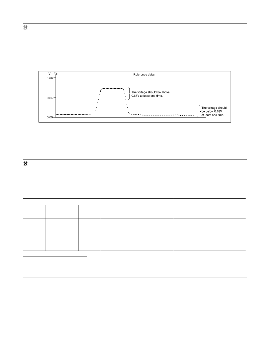
Check the voltage between ECM harness connector terminals under the following conditions.
Is the inspection result normal?
YES
>> INSPECTION END
NO
>> GO TO 4.
4.
CHECK HEATED OXYGEN SENSOR 2-II
Check the voltage between ECM harness connector terminals under the following conditions.
PBIB3458E
ECM
Condition
Voltage
Connector
+
–
Terminal
Terminal
F8
33
[HO2S2 (bank 1)
signal]
35
(Sensor
ground)
Revving up to 4,000 rpm under no load at
least 10 times
The voltage should be above 0.68 V at
least once during this procedure.
The voltage should be below 0.18 V at
least once during this procedure.
34
[HO2S2 (bank 2)
signal]

P0139, P0159 HO2S2
EC-221
< DTC/CIRCUIT DIAGNOSIS >
[VQ35DE]
C
D
E
F
G
H
I
J
K
L
M
A
EC
N
P
O
Is the inspection result normal?
YES
>> INSPECTION END
NO
>> GO TO 5.
5.
CHECK HEATED OXYGEN SENSOR 2-III
Check the voltage between ECM harness connector terminals under the following conditions.
Is the inspection result normal?
YES
>> INSPECTION END
NO
>> GO TO 6.
6.
REPLACE HEATED OXYGEN SENSOR 2
Replace malfunctioning heated oxygen sensor 2.
CAUTION:
• Discard any heated oxygen sensor which has been dropped from a height of more than 0.5 m (19.7
in) onto a hard surface such as a concrete floor; use a new one.
• Before installing new oxygen sensor, clean exhaust system threads using Oxygen Sensor Thread
Cleaner [commercial service tool (J-43897-18 or J-43897-12)] and approved anti-seize lubricant
(commercial service tool).
>> INSPECTION END
ECM
Condition
Voltage
Connector
+
–
Terminal
Terminal
F8
33
[HO2S2 (bank 1)
signal]
35
(Sensor
ground)
Keeping engine at idle for 10 minutes
The voltage should be above 0.68 V at
least once during this procedure.
The voltage should be below 0.18 V at
least once during this procedure.
34
[HO2S2 (bank 2)
signal]
ECM
Condition
Voltage
Connector
+
–
Terminal
Terminal
F8
33
[HO2S2 (bank 1)
signal]
35
(Sensor
ground)
Coasting from 80 km/h (50 MPH) with se-
lector lever in the D position
The voltage should be above 0.68 V at
least once during this procedure.
The voltage should be below 0.18 V at
least once during this procedure.
34
[HO2S2 (bank 2)
signal]

EC-222
< DTC/CIRCUIT DIAGNOSIS >
[VQ35DE]
P0171, P0174 FUEL INJECTION SYSTEM FUNCTION
P0171, P0174 FUEL INJECTION SYSTEM FUNCTION
DTC Logic
INFOID:0000000005536622
DTC DETECTION LOGIC
With the Air/Fuel Mixture Ratio Self-Learning Control, the actual mixture ratio can be brought closely to the
theoretical mixture ratio based on the mixture ratio feedback signal from A/F sensor 1. The ECM calculates
the necessary compensation to correct the offset between the actual and the theoretical ratios.
In case the amount of the compensation value is extremely large (the actual mixture ratio is too lean), the
ECM judges the condition as the fuel injection system malfunction and illuminates the MIL (2 trip detection
logic).
DTC CONFIRMATION PROCEDURE
1.
PRECONDITIONING
If DTC Confirmation Procedure has been previously conducted, always perform the following before conduct-
ing the next test.
1.
Turn ignition switch OFF and wait at least 10 seconds.
2.
Turn ignition switch ON.
3.
Turn ignition switch OFF and wait at least 10 seconds.
>> GO TO 2.
2.
PERFORM DTC CONFIRMATION PROCEDURE-I
1.
Clear the mixture ratio self-learning value. Refer to
EC-20, "MIXTURE RATIO SELF-LEARNING VALUE
CLEAR : Special Repair Requirement"
.
2.
Start engine.
Is it difficult to start engine?
YES
>> GO TO 3.
NO
>> GO TO 4.
3.
RESTART ENGINE
If it is difficult to start engine, the fuel injection system has a malfunction, too.
Crank engine while depressing accelerator pedal.
NOTE:
• When depressing accelerator pedal three-fourths (3/4) or more, the control system does not start the
engine. Do not depress accelerator pedal too much.
Does engine start?
YES
>> Go to
NO
>> Check exhaust and intake air leakage visually.
4.
PERFORM DTC CONFIRMATION PROCEDURE-II
1.
Keep engine idle for at least 5 minutes.
2.
Check 1st trip DTC.
Sensor
Input signal to ECM
ECM function
Actuator
A/F sensor 1
Density of oxygen in exhaust gas
(Mixture ratio feedback signal)
Fuel injection control
Fuel injector
DTC No.
Trouble diagnosis name
DTC detecting condition
Possible cause
P0171
Fuel injection system too
lean (bank 1)
• Fuel injection system does not operate properly.
• The amount of mixture ratio compensation is too
large. (The mixture ratio is too lean.)
• Intake air leakage
• A/F sensor 1
• Fuel injector
• Exhaust gas leakage
• Incorrect fuel pressure
• Lack of fuel
• Mass air flow sensor
• Incorrect PCV hose connection
P0174
Fuel injection system too
lean (bank 2)
P0171, P0174 FUEL INJECTION SYSTEM FUNCTION
EC-223
< DTC/CIRCUIT DIAGNOSIS >
[VQ35DE]
C
D
E
F
G
H
I
J
K
L
M
A
EC
N
P
O
Is 1st trip DTC detected?
YES
>> Go to
NO
>> GO TO 5.
5.
PERFORM DTC CONFIRMATION PROCEDURE-III
1.
Turn ignition switch OFF and wait at least 10 seconds.
2.
Start engine.
3.
Maintain the following conditions for at least 10 consecutive minutes.
Hold the accelerator pedal as steady as possible.
CAUTION:
Always drive vehicle at a safe speed.
4.
Check 1st trip DTC.
Is 1st trip DTC detected?
YES
>> Go to
NO
>> INSPECTION END
Diagnosis Procedure
INFOID:0000000005536623
1.
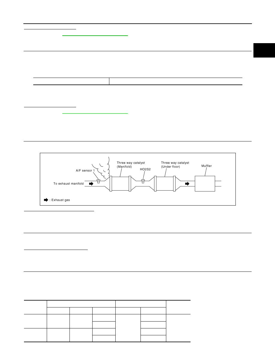
CHECK EXHAUST GAS LEAKAGE
1.
Start engine and run it at idle.
2.
Listen for an exhaust gas leakage before three way catalyst (manifold).
Is exhaust gas leakage detected?
YES
>> Repair or replace malfunctioning part.
NO
>> GO TO 2.
2.
CHECK FOR INTAKE AIR LEAKAGE
1.
Listen for an intake air leakage after the mass air flow sensor.
2.
Check PCV hose connection.
Is intake air leakage detected?
YES
>> Repair or replace malfunctioning part.
NO
>> GO TO 3.
3.
CHECK A/F SENSOR 1 INPUT SIGNAL CIRCUIT
1.
Turn ignition switch OFF.
2.
Disconnect corresponding A/F sensor 1 harness connector.
3.
Disconnect ECM harness connector.
4.
Check the continuity between A/F sensor 1 harness connector and ECM harness connector.
VHCL SPEED SE
50 - 120 km/h (31 - 75 mph)
PBIB1216E
DTC
A/F sensor 1
ECM
Continuity
Bank
Connector
Terminal
Connector
Terminal
P0171
1
F27
1
F8
45
Existed
2
49
P0174
2
F64
1
53
2
57
Нет комментариевНе стесняйтесь поделиться с нами вашим ценным мнением.
Текст