Nissan Qashqai (2007-2010). Manual — part 1368

LIGHTING & TURN SIGNAL SWITCH
EXL-177
< ON-VEHICLE REPAIR >
[XENON TYPE]
C
D
E
F
G
H
I
J
K
M
A
B
EXL
N
O
P
LIGHTING & TURN SIGNAL SWITCH
Exploded View
INFOID:0000000000955513
Removal and Installation
INFOID:0000000001082266
REMOVAL
1.
Remove steering column cover. Refer to
.
2.
While pressing pawls, pull the light & turn signal switch. And disconnect from the switch base.
INSTALLATION
Installation is the reverse order of removal.
1.
Light & turn signal switch
A.
Pawl
JSLIA0092ZZ
EXL-178
< ON-VEHICLE REPAIR >
[XENON TYPE]
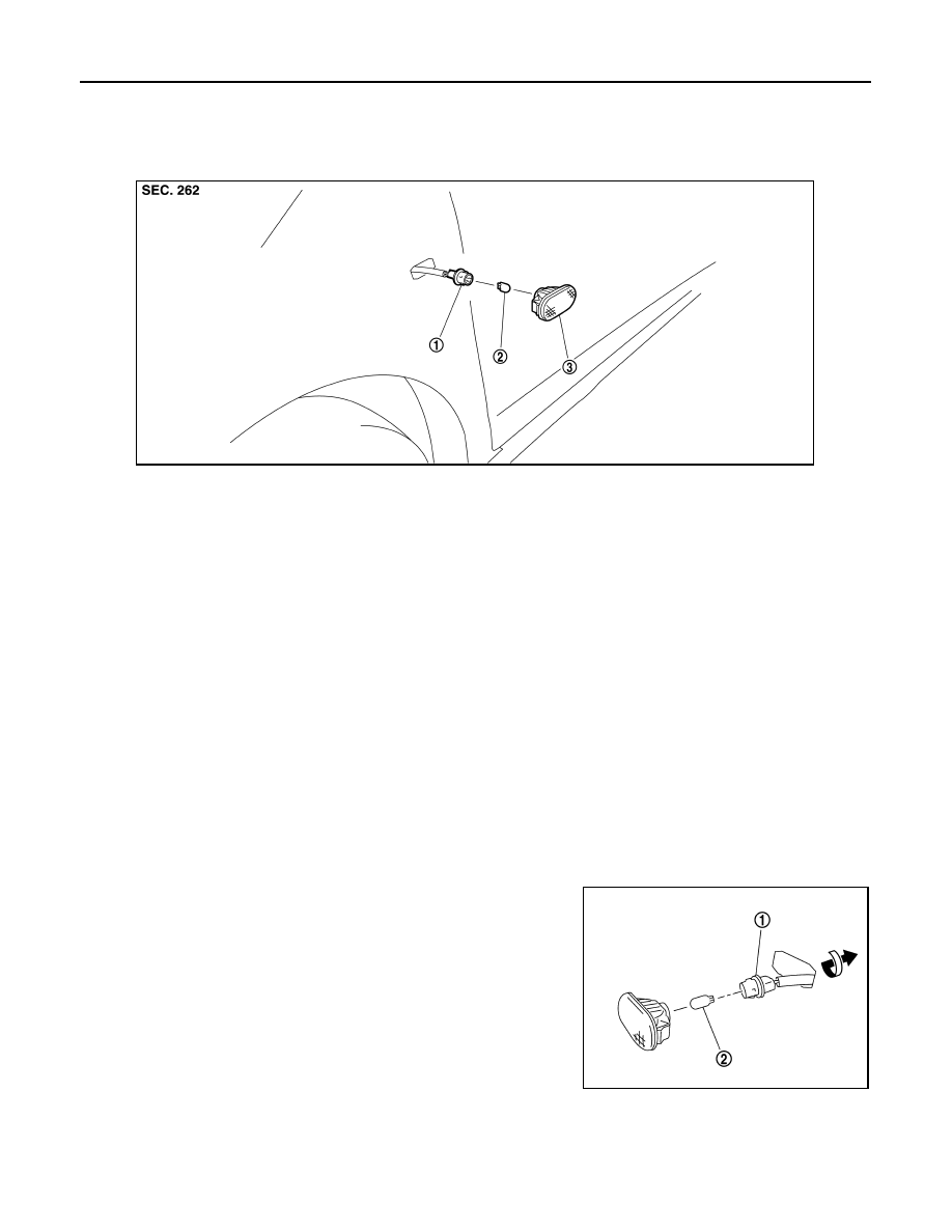
SIDE TURN SIGNAL LAMP
SIDE TURN SIGNAL LAMP
Exploded View
INFOID:0000000000955514
Removal and Installation
INFOID:0000000000955515
CAUTION:
Disconnect battery negative terminal or remove the fuse.
REMOVAL
1.
Insert a spatula or the similar tool under the side turn signal lamp. While pushing the pawl of the lamp, pull
off the lamp from the vehicle.
2.
Disconnect side turn signal lamp connector.
NOTE:
Support side turn signal lamp harness with tape so that it won't fall into the front fender.
INSTALLATION
Install in the reverse order of removal.
Replacement
INFOID:0000000000955516
CAUTION:
Disconnect battery negative terminal or remove the fuse.
SIDE TURN SIGNAL LAMP BULB
1.
Remove the side turn signal lamp.
2.
Rotate the bulb socket (1) counterclockwise and unlock it.
NOTE:
Support the vehicle-side harness of the side turn signal lamp
with tape so that it does not drop inside the front fender.
3.
Remove the bulb (2) from the bulb socket.
1.
Side turn signal lamp bulb socket
2.
Side turn signal lamp bulb
3.
Side turn signal lamp housing
JSLIA0094ZZ
JSLIA0095ZZ
HAZARD SWITCH
EXL-179
< ON-VEHICLE REPAIR >
[XENON TYPE]
C
D
E
F
G
H
I
J
K
M
A
B
EXL
N
O
P
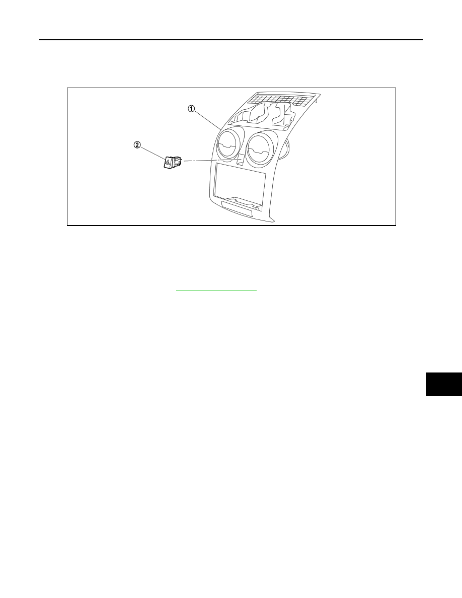
HAZARD SWITCH
Exploded View
INFOID:0000000000955517
Removal and Installation
INFOID:0000000000978418
REMOVAL
1.
Remove the cluster lid C. Refer to
2.
Widen the pawl. Remove hazard switch.
INSTALLATION
Install in the reverse order of removal.
1.
Cluster lid C
2.
Hazard switch
JPLIA0255ZZ
EXL-180
< ON-VEHICLE REPAIR >
[XENON TYPE]
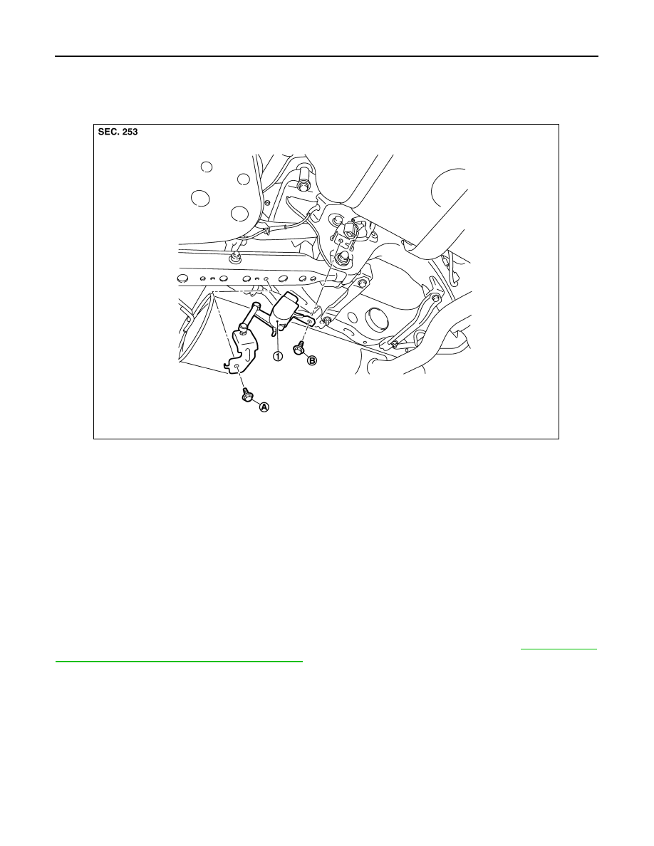
AUTO LEVELIZER CONTROL UNIT
AUTO LEVELIZER CONTROL UNIT
Exploded View
INFOID:0000000000955518
Removal and Installation
INFOID:0000000000955519
Removal
1.
Remove auto levelizer control unit mounting bolt.
2.
Remove sensor lever link bracket bolt.
3.
Disconnect auto levelizer control unit connector.
4.
Remove auto levelizer control unit.
Installation
Install in the reverse order of removal.
CAUTION:
Be sure to perform sensor initialization if auto levelizer control unit is removed. Refer to
SOR INITIALIZE : Special Repair Requirement"
.
1.
Auto levelizer control unit
A.
Sensor lever link bracket bolt
B.
Auto levelizer control unit mounting bolt
JPLIA0173ZZ
Нет комментариевНе стесняйтесь поделиться с нами вашим ценным мнением.
Текст