Nissan Qashqai (2007-2010). Manual — part 1366

FRONT FOG LAMP AIMING ADJUSTMENT
EXL-169
< ON-VEHICLE MAINTENANCE >
[XENON TYPE]
C
D
E
F
G
H
I
J
K
M
A
B
EXL
N
O
P
FRONT FOG LAMP AIMING ADJUSTMENT
Description
INFOID:0000000000978377
PREPARATION BEFORE ADJUSTING
NOTE:
• For details, refer to the regulations in your own country.
• Perform aiming if the vehicle front body has been repaired and/or the headlamp assembly has been
replaced.
Before performing aiming adjustment, check the following.
• Adjust the tire pressure to the specification.
• Fill with fuel, engine coolant and each oil.
• Maintain the unloaded vehicle condition. (Remove luggage from the passenger compartment and the lug-
gage room.)
NOTE:
Do not remove the temporary tire, jack and on-vehicle tool.
• Wipe out dirt on the headlamp.
CAUTION:
Never use organic solvent (thinner, gasoline etc.)
• Ride alone on the driver seat.
AIMING ADJUSTMENT SCREW
• Turn the aiming adjusting screw for adjustment.
• For the position and direction of the adjusting screw, refer to the
figure.
NOTE:
A screwdriver or hexagonal wrench (6 mm) can be used for adjust-
ment.
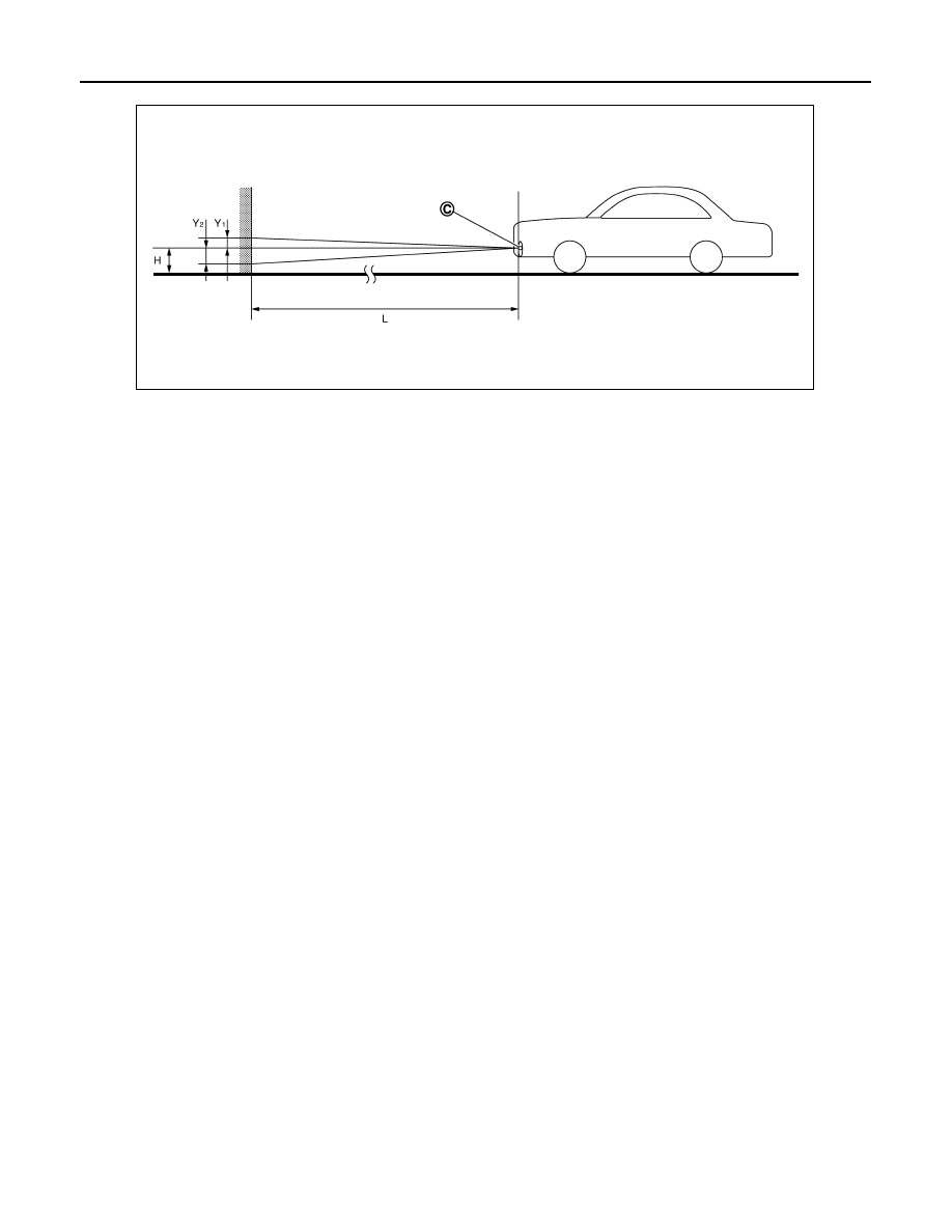
Aiming Adjustment Procedure
INFOID:0000000001102303
1.
Place the screen.
NOTE:
• Stop the vehicle at the perpendicular angle to the wall.
• Set the screen perpendicularly to the ground.
2.
Face the vehicle squarely toward the screen and make the distance between the front fog lamp center
and the screen 10 m (32.8 ft).
3.
Start the engine and illuminate the front fog lamp.
NOTE:
Block light from the front fog lamp that is not being adjusted with a thick fabric or another object, so that it
does not reach the adjustment screen.
CAUTION:
Never cover lens surface with tape, etc. because it is made from plastic.
4.
Use the aiming adjustment screw to adjust the elbow point projected by the front fog lights on the screen,
so that it is within the aiming adjustment area.
Unit: mm (in)
A: UP
B: DOWN
JPLIA0253ZZ
Aiming adjustment area
Vertical direction (Y
1
)
(Upper side from headlamp center height)
Vertical direction (Y
2
)
(Lower side from headlamp center height)
100 (3.94)
200 (7.87)
EXL-170
< ON-VEHICLE MAINTENANCE >
[XENON TYPE]
FRONT FOG LAMP AIMING ADJUSTMENT
C.
Vertical center line of front fog
lamp
H.
Horizontal center line of front fog
lamp
L.
Distance from front fog lamp center to screen
Y
1
.
Aiming adjustment area
(Upper)
Y
2
.
Aiming adjustment area
(Lower)
Distance from headlamp center to screen (L)
: 10 m (32.8 ft)
JPLIA0303ZZ
FRONT COMBINATION LAMP
EXL-171
< ON-VEHICLE REPAIR >
[XENON TYPE]
C
D
E
F
G
H
I
J
K
M
A
B
EXL
N
O
P
ON-VEHICLE REPAIR
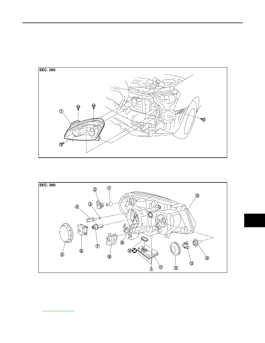
FRONT COMBINATION LAMP
Exploded View
INFOID:0000000000955504
REMOVAL
DISASSEMBLY
Removal and Installation
INFOID:0000000000955505
1.
Front combination lamp
JPLIA0247ZZ
1.
Front turn signal lamp bulb
2.
Front turn signal lamp bulb socket
3.
Parking lamp bulb
4.
Parking lamp bulb socket
5.
Resin cap
6.
Xenon bulb socket
7.
Xenon bulb (LO)
8.
Headlamp aiming motor
9.
Retaining spring
10.
Seal packing
11. HID control unit
12. Back cover
13.
Retaining plate
14. Halogen bulb (HI)
15. Headlamp housing assembly
Refer to
for symbols not described above.
JPLIA0248ZZ

EXL-172
< ON-VEHICLE REPAIR >
[XENON TYPE]
FRONT COMBINATION LAMP
REMOVAL
CAUTION:
Disconnect the battery negative terminal or the fuse.
1.
Remove front bumper fascia. Refer to
2.
Remove the headlamp mounting bolts.
3.
Pull out the headlamp assembly forward the vehicle.
4.
Disconnect the connector before removing the headlamp assembly.
INSTALLATION
Install in the reverse order of removal.
NOTE:
After installation, perform aiming adjustment. Refer to
Replacement
INFOID:0000000000955506
CAUTION:
• Disconnect the battery negative terminal or the fuse.
• After installing the bulb, install the resin cap and the bulb socket securely for watertightness.
HEADLAMP BULB (LO)
1.
Remove the air duct (when replace a left). Keep a service area.
2.
Rotate the resin cap counterclockwise and unlock it.
3.
Rotate the bulb socket counterclockwise and unlock it.
4.
Remove the retaining spring lock. Remove the bulb from the
headlamp.
CAUTION:
Never break the xenon bulb ceramic tube when replacing
the bulb.
HEADLAMP BULB (HI)
1.
Remove the air duct (when replace a left). Keep a service area.
2.
Rotate the back cover counterclockwise and unlock it.
3.
Rotate the retaining plate counterclockwise and unlock it.
4.
Remove the bulb from the headlamp.
PARKING LAMP BULB
1.
Rotate the bulb socket clockwise and unlock it.
2.
Remove the bulb from the bulb socket.
FRONT TURN SIGNAL LAMP BULB
1.
Rotate the bulb socket counterclockwise and unlock it.
2.
Remove the bulb from the bulb socket.
Disassembly and Assembly
INFOID:0000000000955507
DISASSEMBLY
1.
Rotate the resin cap counterclockwise and unlock it.
2.
Rotate the terminal which connect to a socket.
3.
Rotate the xenon bulb socket counterclockwise and unlock it.
4.
Remove the retaining spring lock. Remove the xenon bulb.
5.
Remove the HID control unit installation screw.
6.
Remove the screw. Disconnect the connector from HID control unit.
JPLIA0249ZZ
Нет комментариевНе стесняйтесь поделиться с нами вашим ценным мнением.
Текст