Nissan Qashqai (2007-2010). Manual — part 49
EM-144
< ON-VEHICLE REPAIR >
[MR20DE]
AIR CLEANER AND AIR DUCT
AIR CLEANER AND AIR DUCT
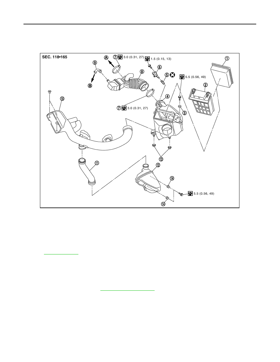
Exploded View
INFOID:0000000000893928
Removal and Installation
INFOID:0000000000893929
REMOVAL
1.
Remove air duct (inlet).
2.
Remove engine cover. Refer to
.
3.
Disconnect mass air flow sensor harness connector.
4.
Disconnect PCV hose.
5.
Remove the battery stay, and then move the battery.
6.
Remove air cleaner case/mass air flow sensor assembly and air duct and resonator assembly disconnect-
ing their joints.
• Add marks as necessary for easier installation.
7.
Remove mass air flow sensor from air cleaner case, if necessary.
CAUTION:
• Never shock mass air flow sensor.
1.
Air cleaner filter
2.
Holder
3.
Grommet
4.
Air cleaner case
5.
O-ring
6.
Mass air flow sensor
7.
Clamp
8.
Air duct and resonator assembly
9.
PCV hose
10. Air duct (inlet)
11.
Air duct
12. Resonator
13. Grommet
14. Grommet
A.
To electric throttle control actuator
B.
To rocker cover
for symbols in the figure.
JPBIA0281GB
AIR CLEANER AND AIR DUCT
EM-145
< ON-VEHICLE REPAIR >
[MR20DE]
C
D
E
F
G
H
I
J
K
L
M
A
EM
N
P
O
• Never disassemble mass air flow sensor.
INSTALLATION
Note the following, and install in the reverse order of removal.
• Align marks. Attach each joint. Screw clamps firmly.
Inspection
INFOID:0000000000893930
INSPECTION AFTER REMOVAL
Inspect air duct and resonator assembly for crack or tear.
• If anything found, replace air duct and resonator assembly.
EM-146
< ON-VEHICLE REPAIR >
[MR20DE]
INTAKE MANIFOLD
INTAKE MANIFOLD
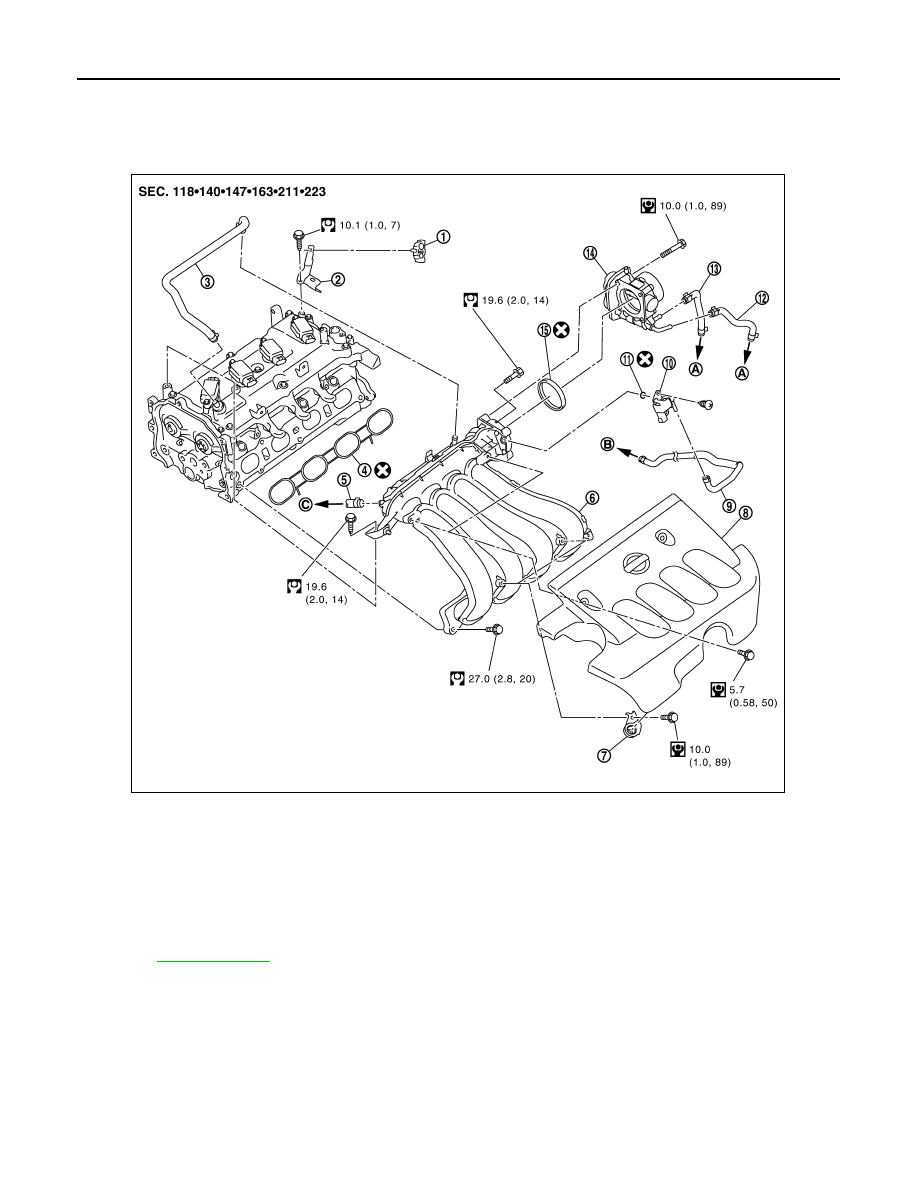
Exploded View
INFOID:0000000000893931
Removal and Installation
INFOID:0000000000893932
REMOVAL
1.
Remove engine cover.
2.
Pull out oil level gauge.
CAUTION:
Cover the oil level gauge guide openings to avoid entry of foreign materials.
3.
Disconnect PCV hose from intake manifold and rocker cover.
1.
Clamp
2.
Harness bracket
3.
PCV hose
4.
Gasket
5.
Vacuum hose
6.
Intake manifold
7.
Bracket
8.
Engine cover
9.
EVAP hose
10.
EVAP canister purge volume control
solenoid valve
11.
O-ring
12. Water hose
13. Water hose
14. Electric throttle control actuator
15. Gasket
A.
To water outlet
B.
To centralized under-floor piping
C.
To brake booster
Refer to
for symbols in the figure.
JPBIA0282GB
INTAKE MANIFOLD
EM-147
< ON-VEHICLE REPAIR >
[MR20DE]
C
D
E
F
G
H
I
J
K
L
M
A
EM
N
P
O
4.
Remove air duct and resonator assembly. Refer to
.
5.
Disconnect vacuum hose from intake manifold. Refer to
.
6.
Disconnect water hoses from electric throttle control actuator, attach blind plug to prevent engine coolant
leakage.
CAUTION:
• Perform this step when the engine is cold.
• Never spill engine coolant on drive belts.
7.
Remove electric throttle control actuator.
CAUTION:
• Handle carefully to avoid any shock to electric throttle control actuator.
• Never disassemble electric throttle control actuator.
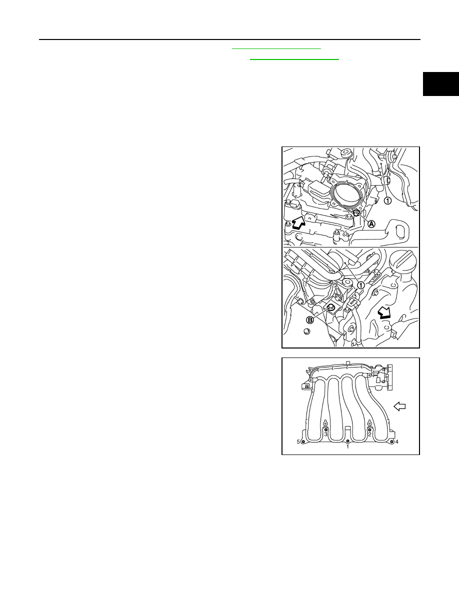
8.
Remove intake manifold (1) with the following procedure:
a.
Loosen and remove intake manifold mounting bolts (A) and (B).
b.
Loosen mounting bolts in reverse order as shown in the figure.
CAUTION:
Cover engine openings to avoid entry of foreign materials.
9.
Remove brackets from intake manifold, if necessary.
10. Remove EVAP canister purge volume control solenoid valve from intake manifold, if necessary.
INSTALLATION
Note the following, and install in the reverse order of removal.
Intake Manifold
1.
Check if gasket is not dropped from the installation groove of intake manifold.
2.
Install intake manifold with the following procedure:
: Engine front
PBIC3939E
: Engine front
PBIC3527J
Нет комментариевНе стесняйтесь поделиться с нами вашим ценным мнением.
Текст