Nissan Qashqai (2007-2010). Manual — part 47
EM-136
< ON-VEHICLE MAINTENANCE >
[MR20DE]
AIR CLEANER FILTER
AIR CLEANER FILTER
Removal and Installation
INFOID:0000000000893922
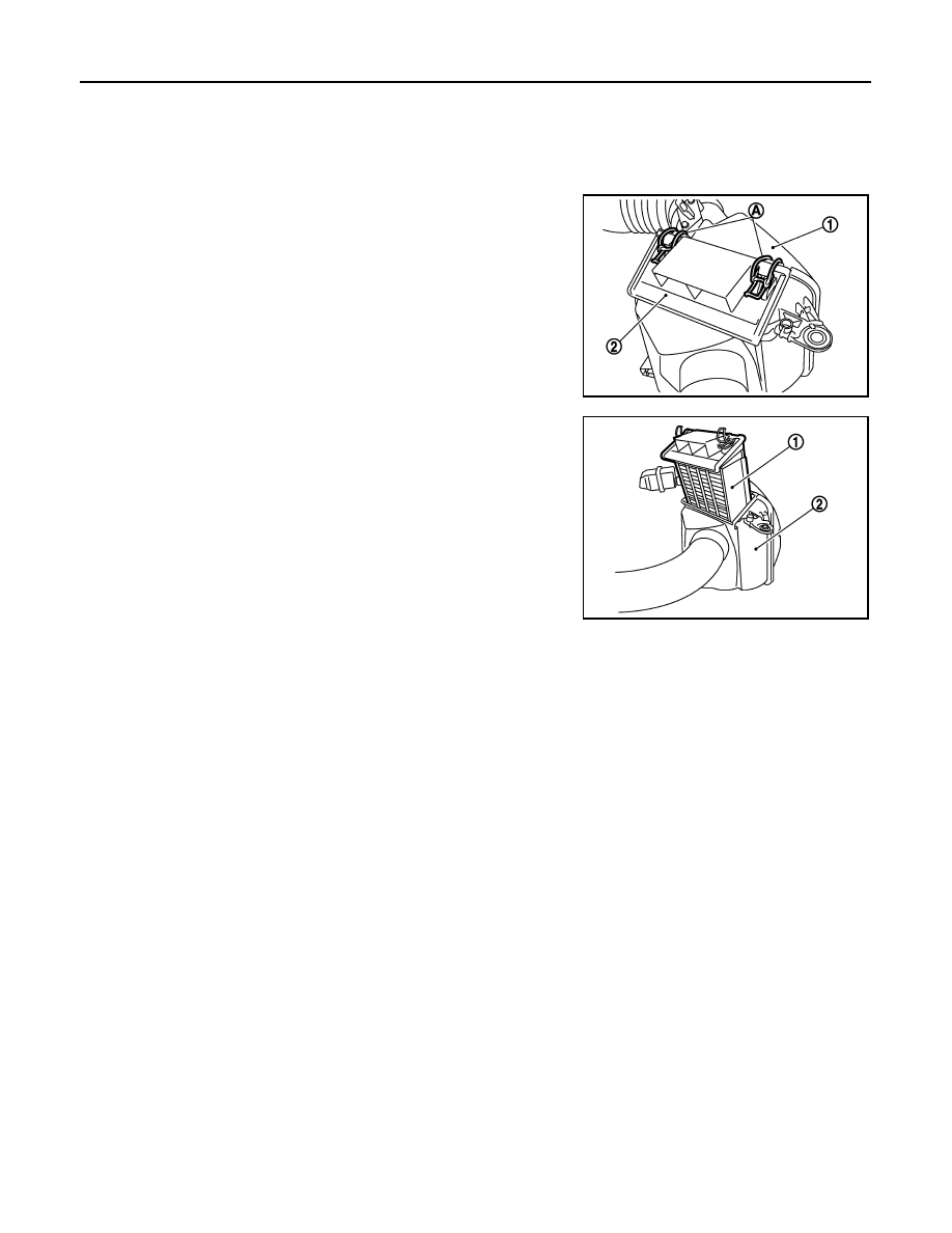
REMOVAL
1.
Unhook clips (A) and remove holder (2) from air cleaner case
(1).
2.
Remove air cleaner filter (1) from air cleaner case (2).
INSTALLATION
Note the following, and install in the reverse order of removal.
• Install the air cleaner filter by aligning the seal with the notch of air cleaner case.
JPBIA0464ZZ
JPBIA0465ZZ
SPARK PLUG
EM-137
< ON-VEHICLE MAINTENANCE >
[MR20DE]
C
D
E
F
G
H
I
J
K
L
M
A
EM
N
P
O
SPARK PLUG
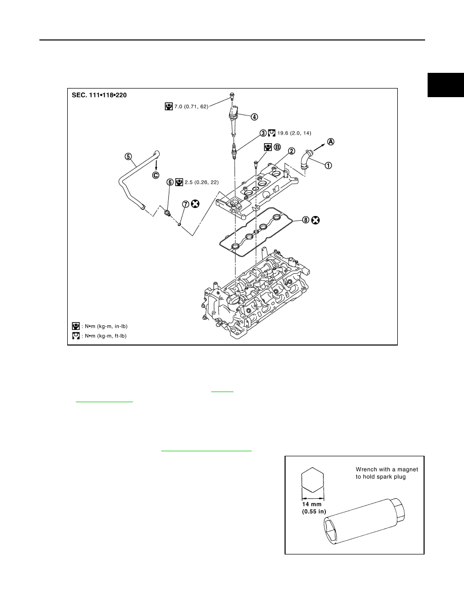
Exploded View
INFOID:0000000000893923
Removal and Installation
INFOID:0000000000893924
REMOVAL
1.
Remove ignition coil. Refer to
2.
Remove spark plug with a spark plug wrench (commercial ser-
vice tool).
INSTALLATION
1.
PCV hose
2.
Rocker cover
3.
Spark plug
4.
Ignition coil
5.
PCV hose
6.
PCV valve
7.
O-ring
8.
Gasket
A.
To air duct
B.
Refer to
C.
To intake manifold
Refer to
PBIC3536J
PBIC3871E
EM-138
< ON-VEHICLE MAINTENANCE >
[MR20DE]
SPARK PLUG
Installation is the reverse order of removal.
Inspection
INFOID:0000000000893925
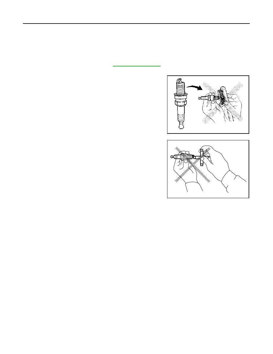
INSPECTION AFTER REMOVAL
Use the standard type spark plug for normal condition.
CAUTION:
• Never drop or shock spark plug.
• Never use a wire brush for cleaning.
• If plug tip is covered with carbon, spark plug cleaner may be
used.
• Checking and adjusting plug gap is not required between
change intervals.
Spark plug (standard)
: Refer to
Cleaner air pressure:
Less than 588 kPa (6 kg/cm
2
, 85 psi)
Cleaning time:
Less than 20 seconds
SMA773C
JPBIA0031ZZ
CAMSHAFT VALVE CLEARANCE
EM-139
< ON-VEHICLE MAINTENANCE >
[MR20DE]
C
D
E
F
G
H
I
J
K
L
M
A
EM
N
P
O
CAMSHAFT VALVE CLEARANCE
Inspection and Adjustment
INFOID:0000000000893926
INSPECTION
Perform inspection as follows after removal, installation or replacement of camshaft or valve-related parts, or if
there is unusual engine conditions regarding valve clearance.
1.
Remove rocker cover. Refer to
2.
Measure the valve clearance with the following procedure:
a.
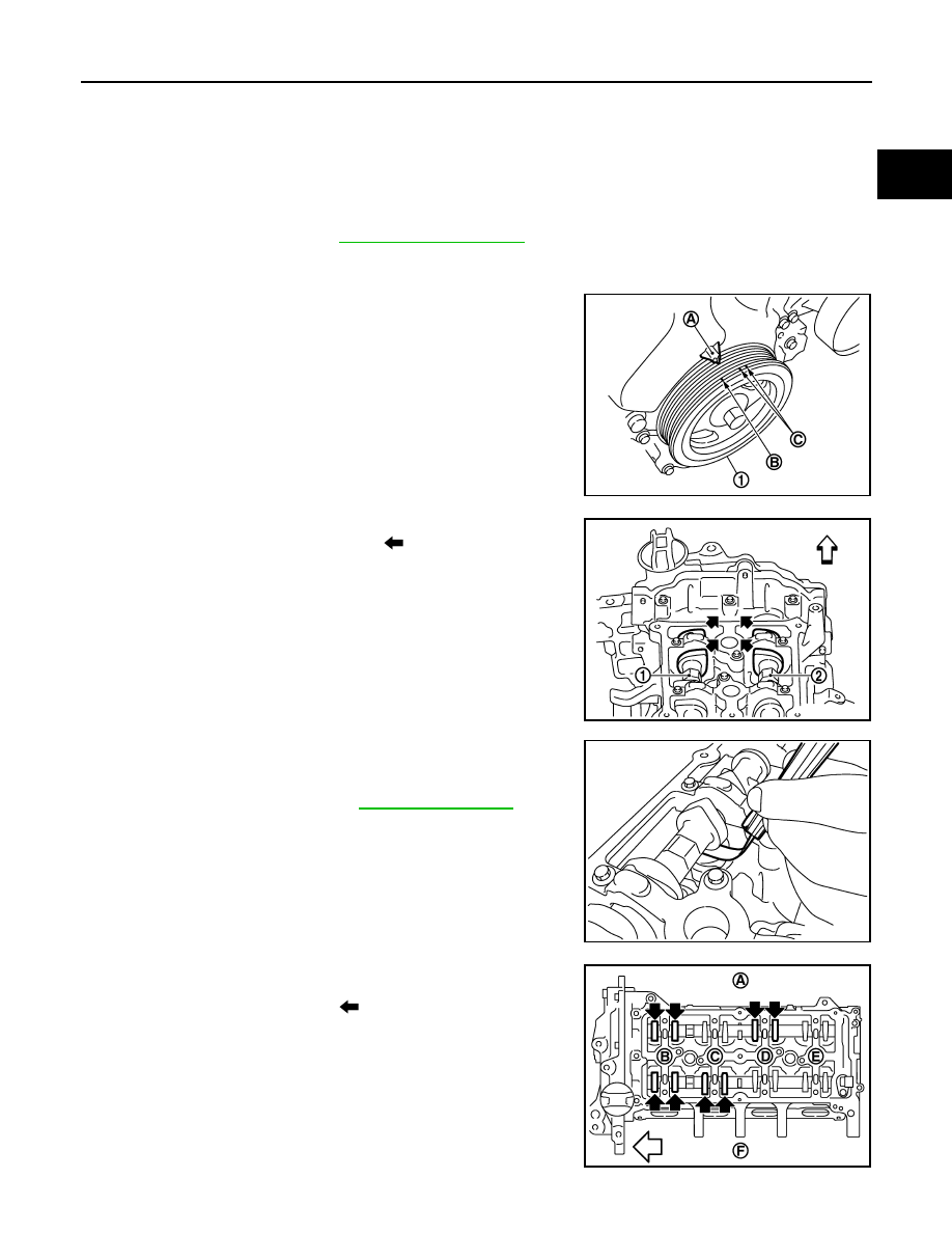
Set No. 1 cylinder at TDC of its compression stroke.
• Rotate crankshaft pulley (1) clockwise and align TDC mark (no
paint) (B) to timing indicator (A) on front cover.
• At the same time, make sure that both intake and exhaust cam
noses of No. 1 cylinder face inside (
) as shown in the figure.
• If they do not face inside, rotate crankshaft pulley once more
(360 degrees) and align as shown in the figure.
b.
Use a feeler gauge, measure the clearance between valve lifter
and camshaft.
• By referring to the figure, measure the valve clearances at
locations marked “
×
” as shown in the table below [locations
indicated with black arrow (
) in the figure] with a feeler
gauge.
C : White paint mark (Not use for service)
PBIC3960E
1
: Camshaft (INT)
2
: Camshaft (EXH)
: Engine front
PBIC3359J
Valve clearance
: Refer to
.
PBIC3192J
A
: Exhaust side
B
: No.1 cylinder
C
: No.2 cylinder
D
: No.3 cylinder
E
: No.4 cylinder
PBIC3193J
Нет комментариевНе стесняйтесь поделиться с нами вашим ценным мнением.
Текст