Nissan Qashqai (2007-2010). Manual — part 48
EM-140
< ON-VEHICLE MAINTENANCE >
[MR20DE]
CAMSHAFT VALVE CLEARANCE
c.
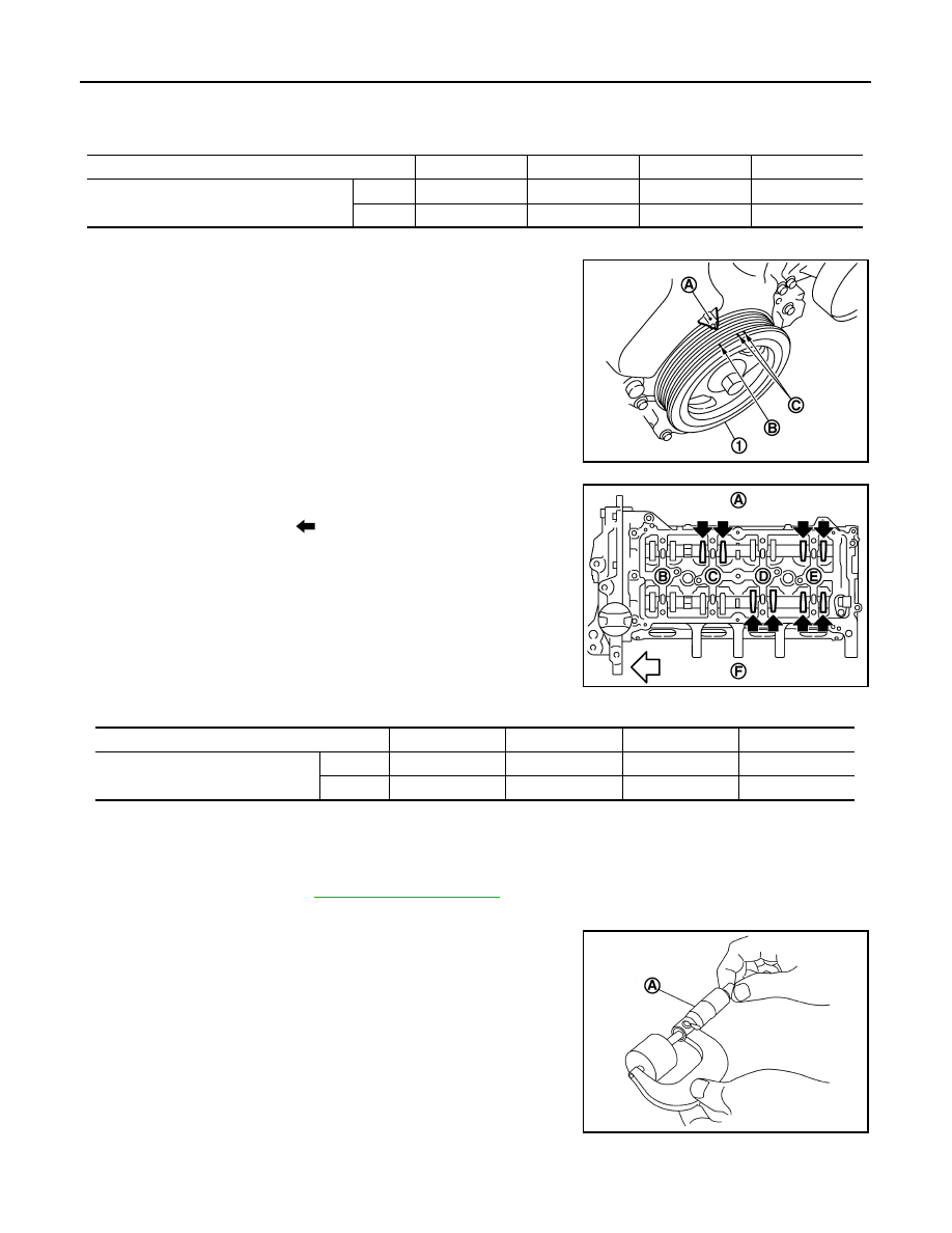
Set No.4 cylinder at TDC of its compression stroke.
• Rotate crankshaft pulley (1) one revolution (360 degrees) and
align TDC mark (no paint) (B) to timing indicator (A) on front
cover.
• By referring to the figure, measure the valve clearance at loca-
tions marked “
×
” as shown in the table below [locations indi-
cated with black arrow (
) in the figure] with a feeler gauge.
3.
If out of standard, perform adjustment. Refer to “ADJUSTMENT”.
ADJUSTMENT
• Perform adjustment depending on selected head thickness of valve lifter.
1.
Remove camshaft. Refer to
2.
Remove valve lifters at the locations that are out of the standard.
3.
Measure the center thickness of the removed valve lifters with a
micrometer (A).
4.
Use the equation below to calculate valve lifter thickness for replacement.
F
: Intake side
: Engine front
Measuring position
No. 1 CYL.
No. 2 CYL.
No. 3 CYL.
No. 4 CYL.
No. 1 cylinder at compression TDC
EXH
×
×
INT
×
×
C : White paint mark (Not use for service)
PBIC3960E
A
: Exhaust side
B
: No.1 cylinder
C
: No.2 cylinder
D
: No.3 cylinder
E
: No.4 cylinder
F
: Intake side
: Engine front
Measuring position
No. 1 CYL.
No. 2 CYL.
No. 3 CYL.
No. 4 CYL.
No. 4 cylinder at compression TDC
EXH
×
×
INT
×
×
PBIC3194J
PBIC3195J
CAMSHAFT VALVE CLEARANCE
EM-141
< ON-VEHICLE MAINTENANCE >
[MR20DE]
C
D
E
F
G
H
I
J
K
L
M
A
EM
N
P
O
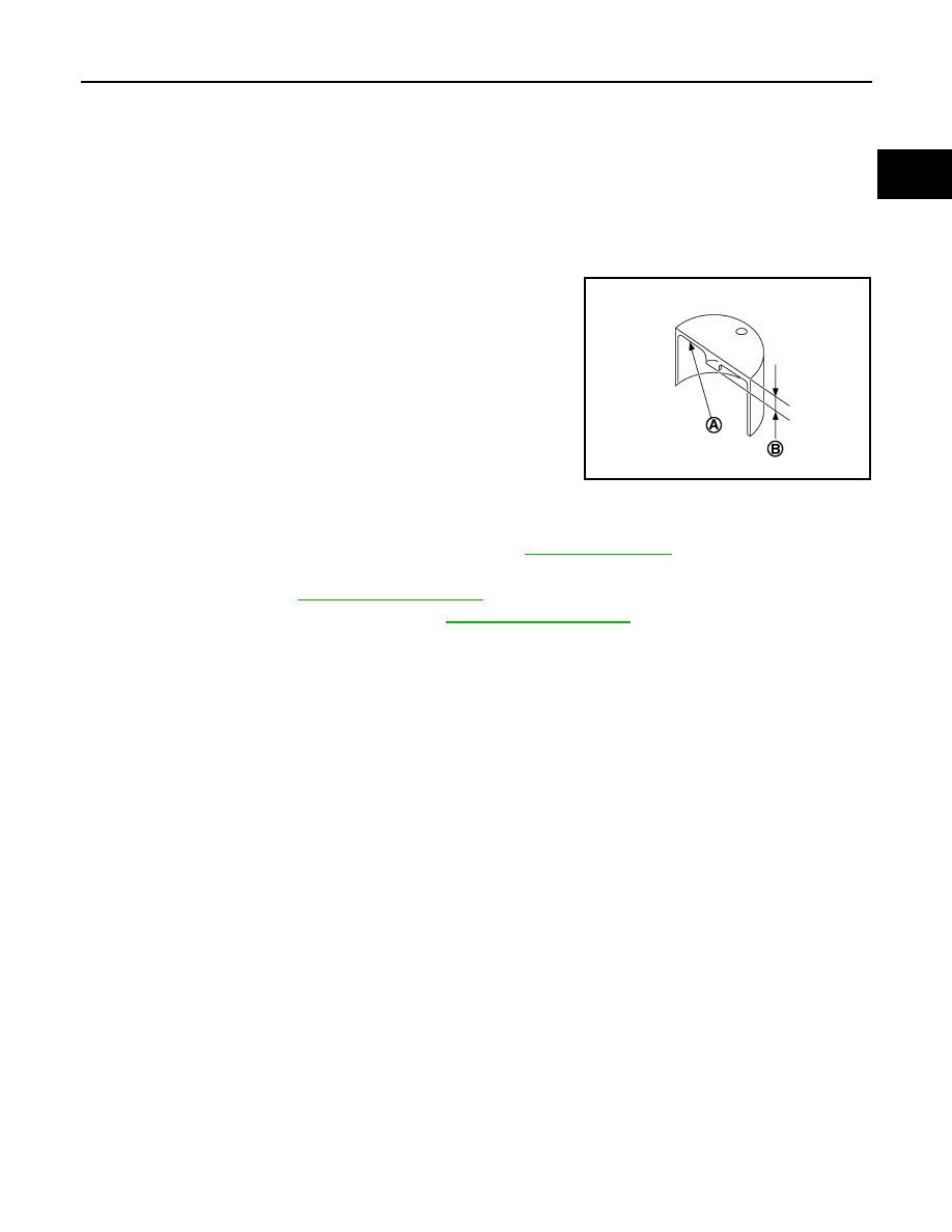
• Thickness of new valve lifter (B) can be identified by stamp
mark (A) on the reverse side (inside the cylinder).
• Stamp mark “302” indicates 3.02 mm (0.118 in) in thickness.
NOTE:
Available thickness of valve lifter: 26 sizes range 3.00 to 3.50 mm (0.1181 to 0.1378 in) in steps of 0.02
mm (0.0008 in) (when manufactured at factory). Refer to
5.
Install the selected valve lifter.
6.
Install camshaft. Refer to
7.
Install timing chain and related parts. Refer to
8.
Manually rotate crankshaft pulley a few rotations.
9.
Make sure that the valve clearances is within the standard. Refer to “INSPECTION”.
10. Install remaining parts in the reverse order of removal.
11. Warm up the engine, and check for unusual noise and vibration.
Valve lifter thickness calculation:
t = t
1
+ (C
1
– C
2
)
t
= Valve lifter thickness to be replaced
t
1
= Removed valve lifter thickness
C
1
= Measured valve clearance
C
2
= Standard valve clearance:
Intake
: 0.30 mm (0.012 in)
Exhaust
: 0.33 mm (0.013 in)
PBIC3196J
EM-142
< ON-VEHICLE MAINTENANCE >
[MR20DE]
COMPRESSION PRESSURE
COMPRESSION PRESSURE
Inspection
INFOID:0000000000893927
1.
Warm up engine thoroughly. Then, stop it.
2.
Release fuel pressure. Refer to
.
3.
Remove ignition coil and spark plug from each cylinder. Refer to
4.
Connect engine tachometer (not required in use of CONSULT-III).
5.
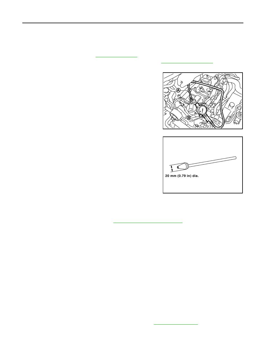
Install compression gauge (B) with an adapter (A) (commercial
service tool) onto spark plug hole.
• Use the adapter whose picking up end inserted to spark plug
hole is smaller than 20 mm (0.79 in) in diameter. Otherwise, it
may be caught by cylinder head during removal.
6.
With accelerator pedal fully depressed, turn ignition switch to “START” for cranking. When the gauge
pointer stabilizes, read the compression pressure and the engine rpm. Perform these steps to check each
cylinder.
CAUTION:
Always use a fully changed battery to obtain the specified engine speed.
• If the engine speed is out of the specified range, check battery liquid for proper gravity. Check the
engine speed again with normal battery gravity.
• If compression pressure is below minimum value, check valve clearances and parts associated with
combustion chamber (valve, valve seat, piston, piston ring, cylinder bore, cylinder head, cylinder head
gasket). After the checking, measure compression pressure again.
• If some cylinder has low compression pressure, pour small amount of engine oil into the spark plug hole
of the cylinder to re-check it for compression.
- If the added engine oil improves the compression, piston rings may be worn out or damaged. Check pis-
ton rings and replace if necessary.
- If the compression pressure remains at low level despite the addition of engine oil, valves may be mal-
functioning. Check valves for damage. Replace valve or valve seat accordingly.
• If two adjacent cylinders have respectively low compression pressure and their compression remains
low even after the addition of engine oil, cylinder head gaskets are leaking. In such a case, replace cyl-
inder head gaskets.
7.
After inspection is completed, install removed parts.
8.
Start the engine, and make sure that the engine runs smoothly.
9.
Perform trouble diagnosis. If DTC appears, erase it. Refer to
PBIC3541J
SBIA0533E
Compression pressure
: Refer to
DRIVE BELT AUTO-TENSIONER
EM-143
< ON-VEHICLE REPAIR >
[MR20DE]
C
D
E
F
G
H
I
J
K
L
M
A
EM
N
P
O
ON-VEHICLE REPAIR
DRIVE BELT AUTO-TENSIONER
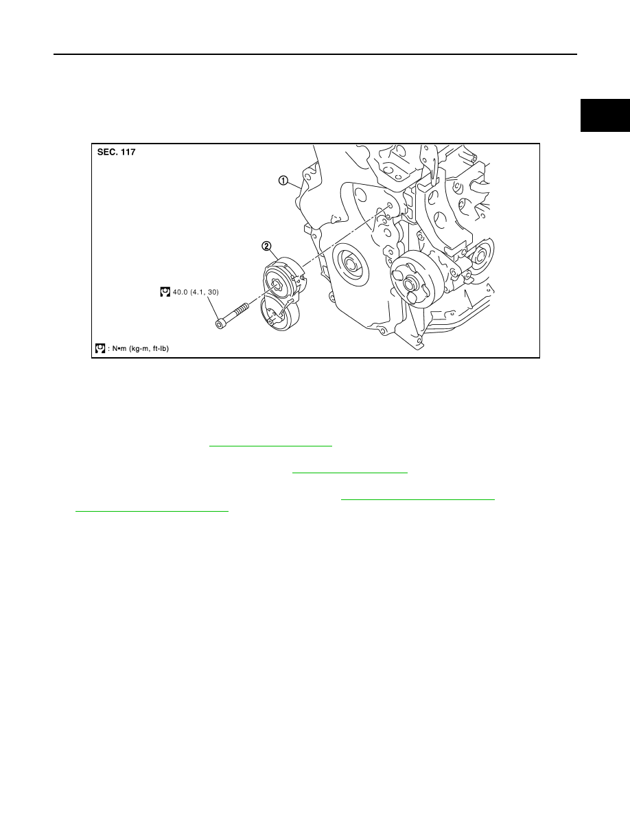
Exploded View
INFOID:0000000000902357
Removal and Installation
INFOID:0000000000902358
Removal
1.
Remove drive belt. Refer to
• Keep drive belt auto-tensioner pulley arm locked after drive belt is removed.
2.
Remove front fender protector (RH). Refer to
3.
Support the bottom surface of engine using a transmission jack, and then remove the engine mounting
stay and the engine mounting insulator (RH). Refer to
(CVT models).
4.
Loosen mounting bolt and remove drive belt auto-tensioner.
• Lift the front side of the engine with a jack sustaining engine base to remove mounting bolt.
NOTE:
Use TORX socket (size T50).
Installation
Installation is the reverse order of removal.
CAUTION:
When installing drive belt auto-tensioner, be careful not to interfere with water pump pulley.
1.
Front cover
2.
Drive belt auto-tensioner
PBIC3937E
Нет комментариевНе стесняйтесь поделиться с нами вашим ценным мнением.
Текст